
Light source for optical fibre grating

A fiber Bragg grating and light source technology, applied in the coupling of optical waveguide, optics, light guide, etc., can solve the problems of large loss of optical path system, unstable output spectrum, narrow fluorescent spectral line, etc.

Inactive Publication Date: 2005-09-21
CHANGCHUN INST OF OPTICS FINE MECHANICS & PHYSICS CHINESE ACAD OF SCI
View PDF0 Cites 1 Cited by
  • Summary
  • Abstract
  • Description
  • Claims
  • Application Information

AI Technical Summary

Problems solved by technology

[0004] In order to solve the problem that the light source in the above background technology adopts a mixed structure of optical fiber and lens, this structure has the problems of unstable output spectrum, large influence by environment, temperature, stress and other factors, narrow fluorescent spectral line, and large loss in optical system transmission; this paper The purpose of the invention is to provide a light source for fiber grating for fiber grating waveguide

Method used


Image

  • Light source for optical fibre grating
  • Light source for optical fibre grating
  • Light source for optical fibre grating

Examples


specific Embodiment approach

[0014] The specific embodiment: the specific embodiment of the present invention will be described below with reference to the accompanying drawings

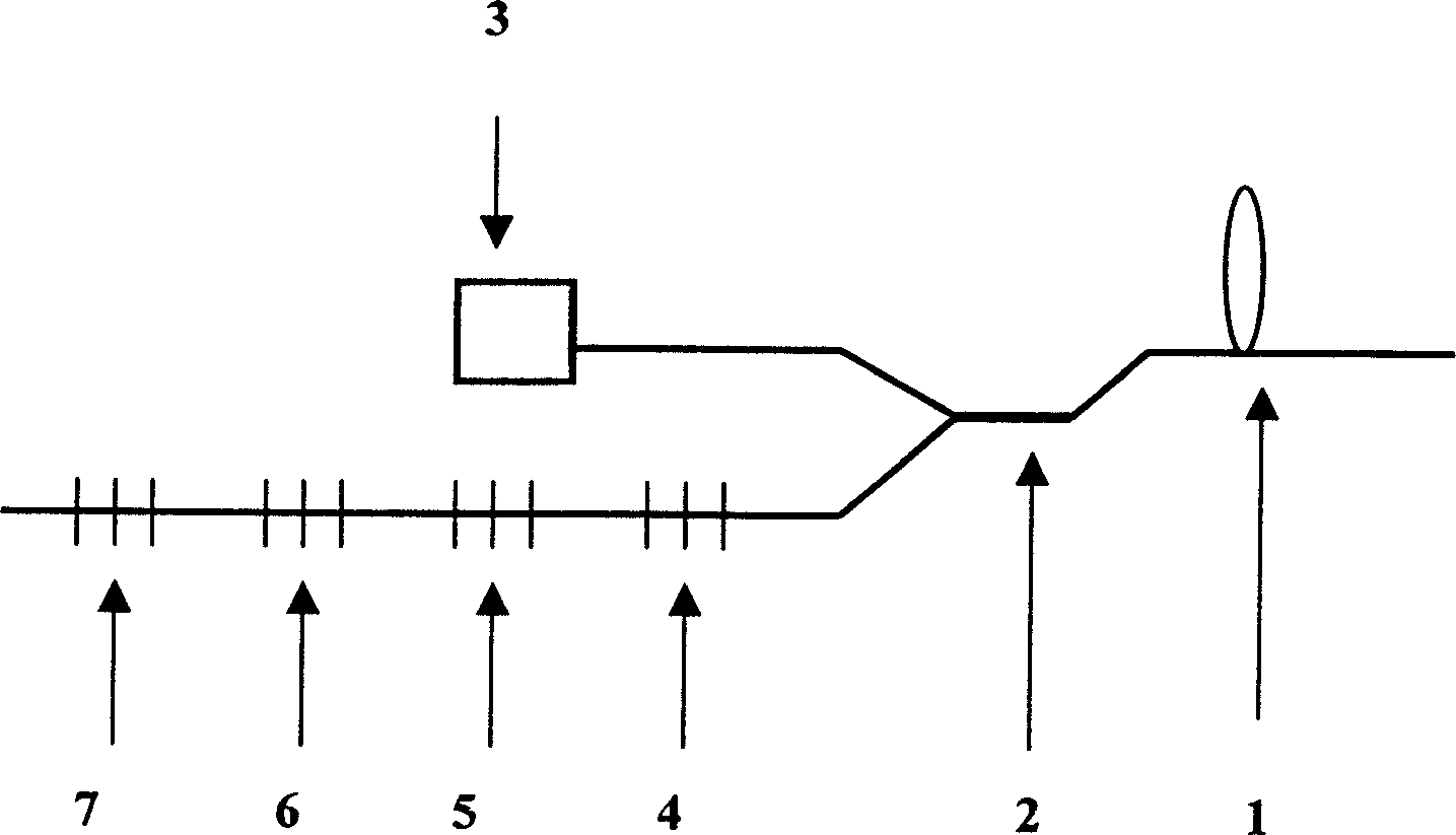
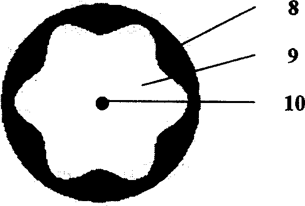
[0015] The present invention consists of a doped fiber 1, a wavelength division multiplexer 2, a light source 3, a fiber grating one 4, a fiber grating two 5, a fiber grating three 6, and a fiber grating four 7; the structure of the doped fiber 1 includes: an outer cladding 8 , inner cladding 9, fiber core 10.

[0016] Doped optical fiber 1 uses ytterbium-doped aluminum-silicon ion optical fiber material or boron oxide ion optical fiber material as the gain medium, and selects a section of active optical fiber doped with ytterbium-aluminum-silicon ion with a length of 10 meters as doped optical fiber 1, wherein the outer cladding 8 is a diameter of 125 μm, the diameter of the inner cladding 9 is 80-95 μm, and the diameter of the fiber core 10 is 4-7.5 μm. The cut-off wavelength is 900nm, the background loss is 19 ions.cm -3 . ...


PUM


Abstract

This invention relates to measurement and control fiber grating wave guide structure source, which comprises the following steps: mixed fiber 1, wavelength-division multiplier 2, light source 3, fiber and grating 4, 5, 6 and 7. The invention is compatible to the fiber system to realize the super fluorescence fiber and light source process uses wavelength multiplier and four-fiber grating structure to get the high energy wide spectrum fiber source and changes the spectrum width according to design needs and provides signal source of different width to form random spectrum wide super structure light source.

Description

Technical field: [0001] The invention belongs to the technical field of preparation of optical fiber gratings in optical waveguide structures, and relates to a light source for measuring and controlling optical fiber grating waveguide structures. Background technique: [0002] Since HILL et al. discovered the photosensitive grating effect of germanium-doped silica fiber, MELTZ et al. developed the technology of writing photorefractive fiber grating on the side of ultraviolet UV light. It has had a major impact on optical fiber communication. [0003] Fiber Bragg Grating is a kind of fiber passive device, and its appearance makes it possible to develop various all-fiber devices (such as fiber lasers, all-fiber filters, etc.). In the manufacture and measurement of fiber gratings, an external control light source is required to observe and control the reflection and transmission spectra of fiber gratings. In the past, light-emitting diodes (LEDs) were used as light sources fo...

Claims


Application Information

Patent Timeline
Patent Type & Authority Applications(China)
IPC IPC(8): G02B6/124G02B6/34H04J14/02
Inventor 张亮秦莉王立军
Owner CHANGCHUN INST OF OPTICS FINE MECHANICS & PHYSICS CHINESE ACAD OF SCI
Learn More