Adjustable high temperature condensate water circulating and recovering system and recovering method
A high-temperature condensation and adjustable technology, applied in steam/steam condensers, siphon pipes, machines/engines, etc., can solve the problems of reduced pressure difference, failure of heat engine to work normally, poor siphon effect, etc., to achieve reduced pressure difference and siphon volume Increased, pressure-reduced effects
- Summary
- Abstract
- Description
- Claims
- Application Information
AI Technical Summary
Problems solved by technology
Method used
Image

Examples
Embodiment 1
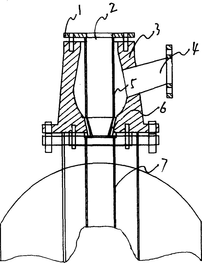
[0012] Example 1: Refer to the attached figure 1 . Adjustable high-temperature condensate water circulation siphon body. The siphon body 3 has a three-way structure and is an integral casting structure or an integral injection molding structure or an integral molding structure or a split welding structure. The inner cavity of the siphon body is curved (in a concave arc) Spherical surface), the siphon body 3 and the lower end tube wall of the siphon tube 5 are tapered, and the tapering directions are opposite and matched. The manufacturing process is based on the existing technology and will not be described here. The siphon tube 5 is composed of a suction tube and a flange 1 and is located in the siphon body 3 through the upper end opening of the siphon body. The lower end tube wall of the siphon tube 5 and the inner wall of the lower end opening of the siphon body 3 form a high-temperature condensate circulation channel 6----- -Both the siphon body 3 and the lower end of the sip...
Embodiment 2
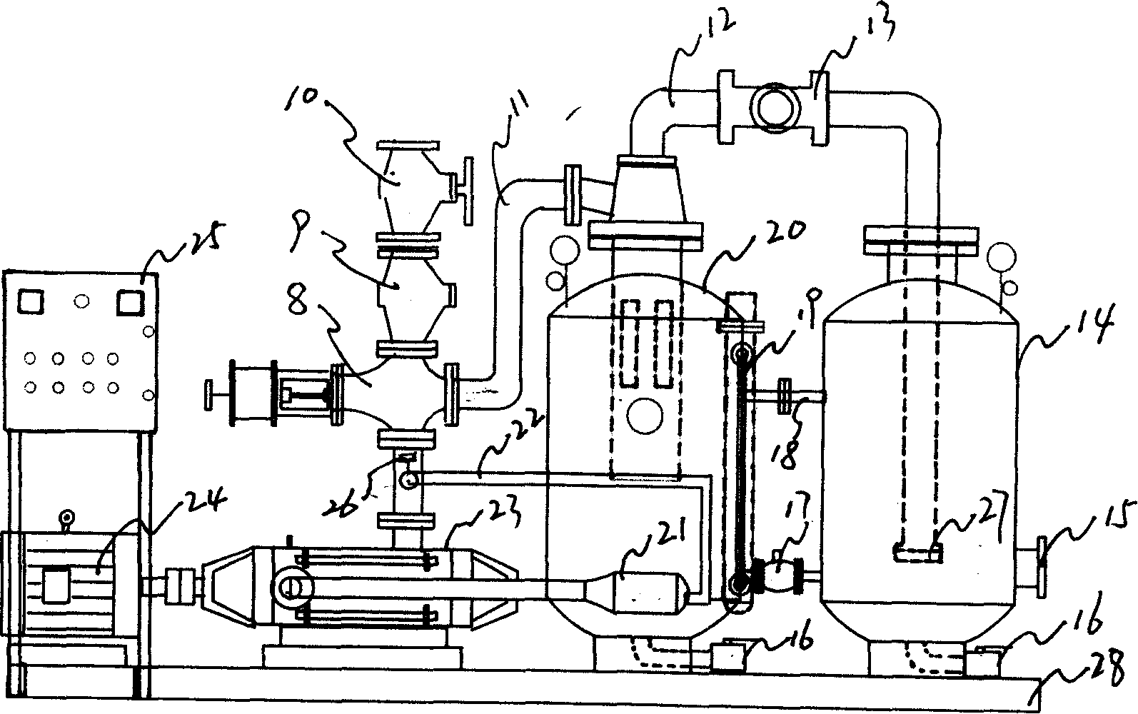
[0013] Example 2: Refer to the attached Figure 1~3 . On the basis of embodiment 1, an adjustable high-temperature condensate recovery system composed of an adjustable high-temperature condensate circulating siphon body includes a power distribution box 25, and the lower end of the adjustable high-temperature condensate circulating siphon body is in communication with a water tank 20, The upper end port of the siphon tube 5 in the adjustable high-temperature condensate water circulation siphon body is communicated with the water storage tank 14 through the connecting pipe 12, and the end of the connecting pipe in the water storage tank 14 is equipped with a check valve 27. The water storage tank 20 and the water storage tank 14 are installed on the base 28, and the bottoms of which are respectively equipped with a drain valve 16. The circulation pressure pipe port of the adjustable high temperature condensate water circulation siphon body passes through the circulation connecting p...
Embodiment 3
[0014] Embodiment 3: Adjustable high-temperature condensate recovery method, open the communication valve 17, and the high-temperature condensate entering the water storage tank 14 from the high-temperature condensate water inlet 15 enters the water storage tank 20 through the communication valve 17, and the high-temperature and high-pressure water pump 23, After the high temperature and high pressure water pump 23 is working normally, close the communication valve 17, the high temperature condensate enters the adjustable high temperature condensate circulation siphon through the three-way pneumatic valve 8, and the circulation connecting pipe 11, and circulates through the adjustable high temperature condensate circulation siphon. The flow channel 6 produces a siphon, and the condensed water in the water storage tank 14 enters the water storage tank 20 through the connecting pipe 12, and when the condensate water in the water storage tank 20 reaches the set amount, it is discharg...
PUM
 Abstract
Description
Claims
Application Information
 - R&D
- Intellectual Property
- Life Sciences
- Materials
- Tech Scout
- Unparalleled Data Quality
- Higher Quality Content
- 60% Fewer Hallucinations
Browse by: Latest US Patents, China's latest patents, Technical Efficacy Thesaurus, Application Domain, Technology Topic, Popular Technical Reports.
© 2025 PatSnap. All rights reserved.Legal|Privacy policy|Modern Slavery Act Transparency Statement|Sitemap|About US| Contact US: help@patsnap.com