Method for measuring atomic force microscope needle type radius using single wall carbon nano tube
A technology of single-walled carbon nanotubes and atomic force microscopy, applied in measuring devices, scanning probe technology, instruments, etc., can solve the problems of poor accuracy, complex measurement and calculation, etc.
- Summary
- Abstract
- Description
- Claims
- Application Information
AI Technical Summary
Problems solved by technology
Method used
Image
Examples
specific Embodiment approach 1
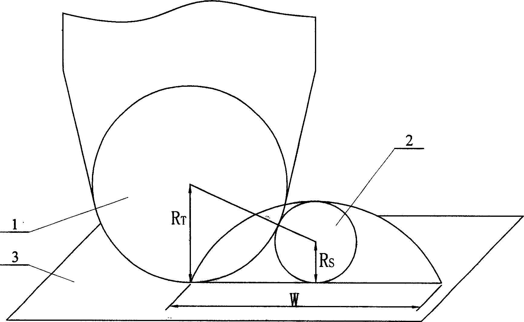
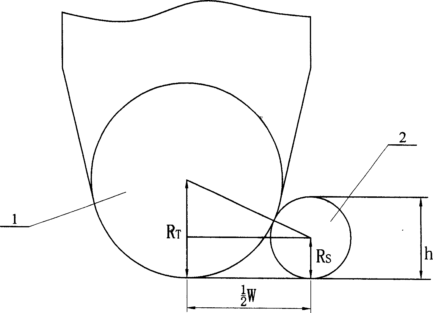
[0005] Specific implementation mode one: the following combination figure 1 and figure 2 This embodiment will be specifically described. This embodiment is realized through the following steps: one, the single-walled carbon nanotubes 2 with a diameter of 1 to 5 nm are deposited on the surface of the mica sheet 3; two, the measurement width w and the measured width of the single-walled carbon nanotubes 2 are measured by an atomic force microscope The height h of the single-walled carbon nanotube 2, the needle tip used to measure the single-walled carbon nanotube on the atomic force microscope is the needle tip 1 to be tested, and the height h of the single-walled carbon nanotube 2 is the height of the single-walled carbon nanotube 2 on the cross section. The diameter is 2Rs; during measurement, the needle tip 1 to be tested is brought into contact with the single-walled carbon nanotube 2, and it is best to select a single-walled carbon nanotube 2 whose cross-sectional radius ...
specific Embodiment approach 2
[0007] Specific embodiment 2: The difference between this embodiment and specific embodiment 1 is that step 1 is realized through the following steps: 1. Weigh 0.002 g of single-walled carbon nanotubes and dissolve them in 10 ml of absolute ethanol to form a concentration of 2.0 ×10 -4 g / ml dilute solution; ② Treat the prepared dilute solution with an ultrasonic wave with a frequency of 60KHZ for 1 hour at 25°C to separate the single-walled carbon nanotubes in the solution; ③ Take three drops of the solution and add it dropwise to a new On the surface of the stripped mica sheet 3, adjust the distribution density of carbon nanotubes by controlling the amount of drop to make the distribution density within 5×5 μm 2 At least one carbon nanotube 2 exists within the range. This embodiment makes the online measurement of the needle tip to be tested more convenient.
specific Embodiment approach 3
[0008] Specific embodiment three: the difference between this embodiment and specific embodiment one is that it also includes the following steps: selecting a plurality of single-walled carbon nanotubes, measuring and calculating the corresponding single-walled carbon nanotubes to be tested respectively. The value of the tip radius, and then calculate the average value of these values as the final radius value of the tip to be tested. In this way, accidental errors can be eliminated and the measured needle tip radius value can be more accurate. Table 1 is the tip radius calculated from W and h of different single-walled carbon nanotubes measured by an atomic force microscope (AFM) equipped with the same tip to be tested
[0009] Single-walled carbon nanotubes1 Single-walled carbon nanotubes2 Single-walled carbon nanotubes3
[0010] Width (W) 24.5nm 18.3nm 14.5nm
[0011] Height (h) 4.3nm 2.5nm 1.51nm
[0012] Tip radius (R T ) 17.4nm 16.7nm 17.3nm
[...
PUM
| Property | Measurement | Unit |
|---|---|---|
| Diameter | aaaaa | aaaaa |
Abstract
Description
Claims
Application Information
 - R&D
- Intellectual Property
- Life Sciences
- Materials
- Tech Scout
- Unparalleled Data Quality
- Higher Quality Content
- 60% Fewer Hallucinations
Browse by: Latest US Patents, China's latest patents, Technical Efficacy Thesaurus, Application Domain, Technology Topic, Popular Technical Reports.
© 2025 PatSnap. All rights reserved.Legal|Privacy policy|Modern Slavery Act Transparency Statement|Sitemap|About US| Contact US: help@patsnap.com


