
Swinging retarding immersion type lens electron optics focusing, deflection and signal collection system and method

A technology of objective lens and deceleration field, which is applied in the direction of radiation conversion chemical element device, beam/ray deflection device, beam/ray focusing/reflection device, etc., which can solve the problem of increasing process, increasing turnaround time of integrated circuits, viewing and measuring Long sample time is required to achieve high resolution, improve signal quality, and reduce time

Inactive Publication Date: 2005-06-22
ASML NETHERLANDS BV
View PDF0 Cites 14 Cited by
  • Summary
  • Abstract
  • Description
  • Claims
  • Application Information

AI Technical Summary

Problems solved by technology

As a result, detection can only be performed simultaneously on relatively small sample portions without repositioning the sample
Second, the time required to inspect, view and measure a sample is substantially long because of the inherently small deflection range
This not only results in increased IC turnaround time, but also increases the cost of process, test, inspection, troubleshooting and production

Method used


Image

  • Swinging retarding immersion type lens electron optics focusing, deflection and signal collection system and method
  • Swinging retarding immersion type lens electron optics focusing, deflection and signal collection system and method
  • Swinging retarding immersion type lens electron optics focusing, deflection and signal collection system and method

Examples


Embodiment Construction

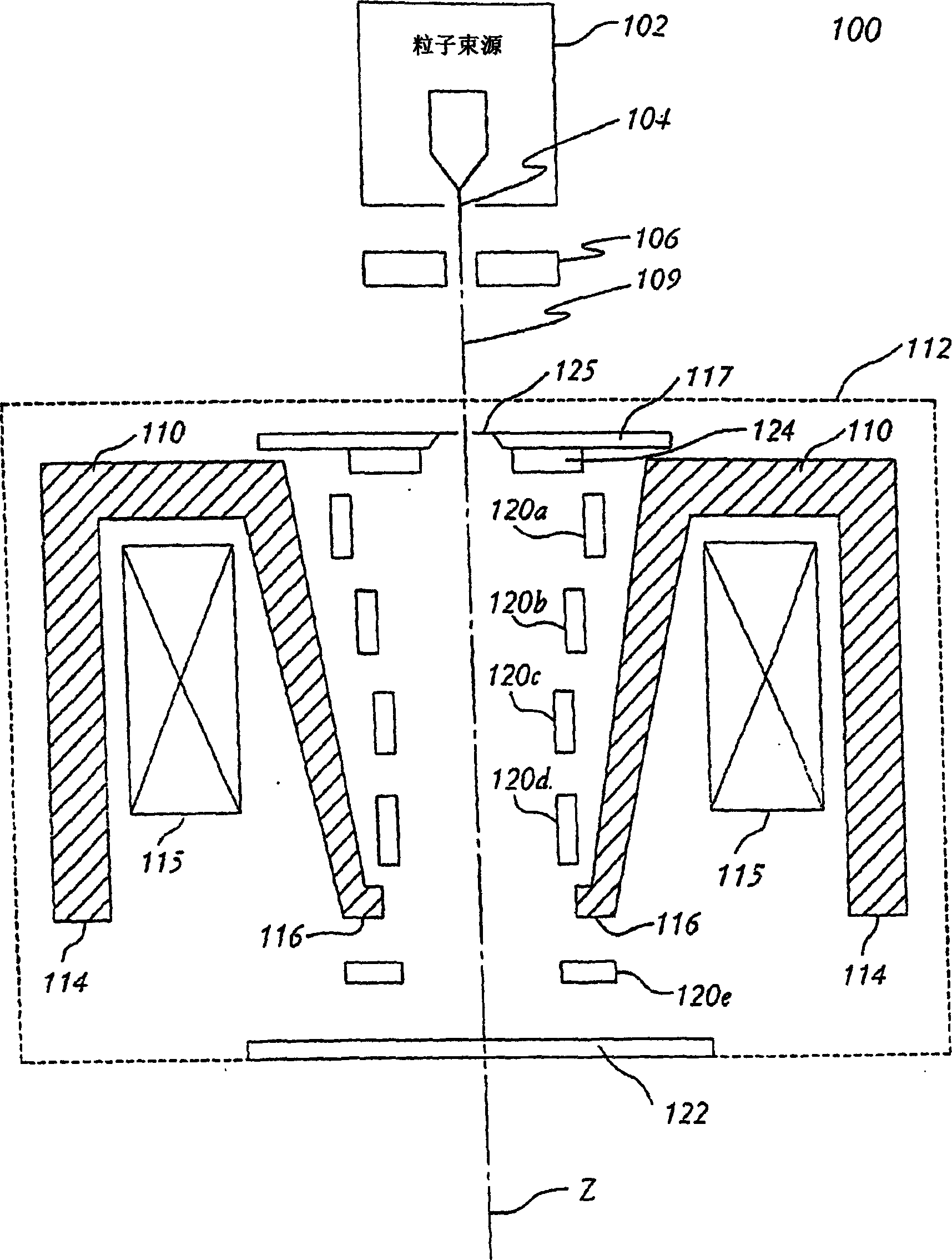
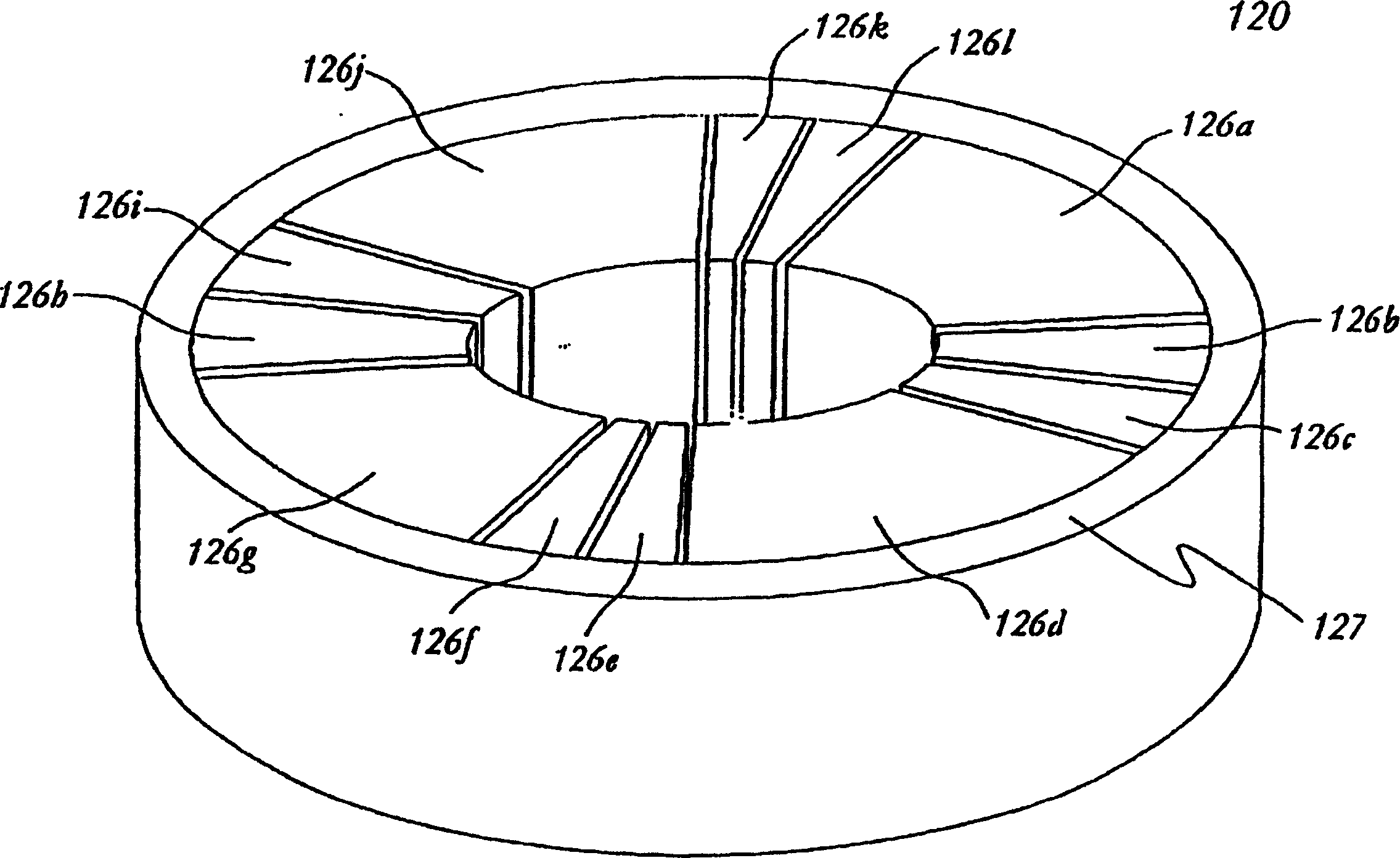
[0023] figure 1 An embodiment of a scanning electron microscope 100 according to the invention is shown. In this embodiment, a scanning electron microscope 100 includes a particle beam source 102 having a virtual source point 104 (i.e., an effective source point for particles), an anode 106 having a magnetic lens therein and a plurality of deflection units 120a-120e The objective lens system 112 . For reference purposes, a beam axis 109 is defined as the line connecting the particle beam source 102 to the sample 122 and is designated as the Z-axis, with the X and Y-axes defining a plane transverse to the Z-axis.

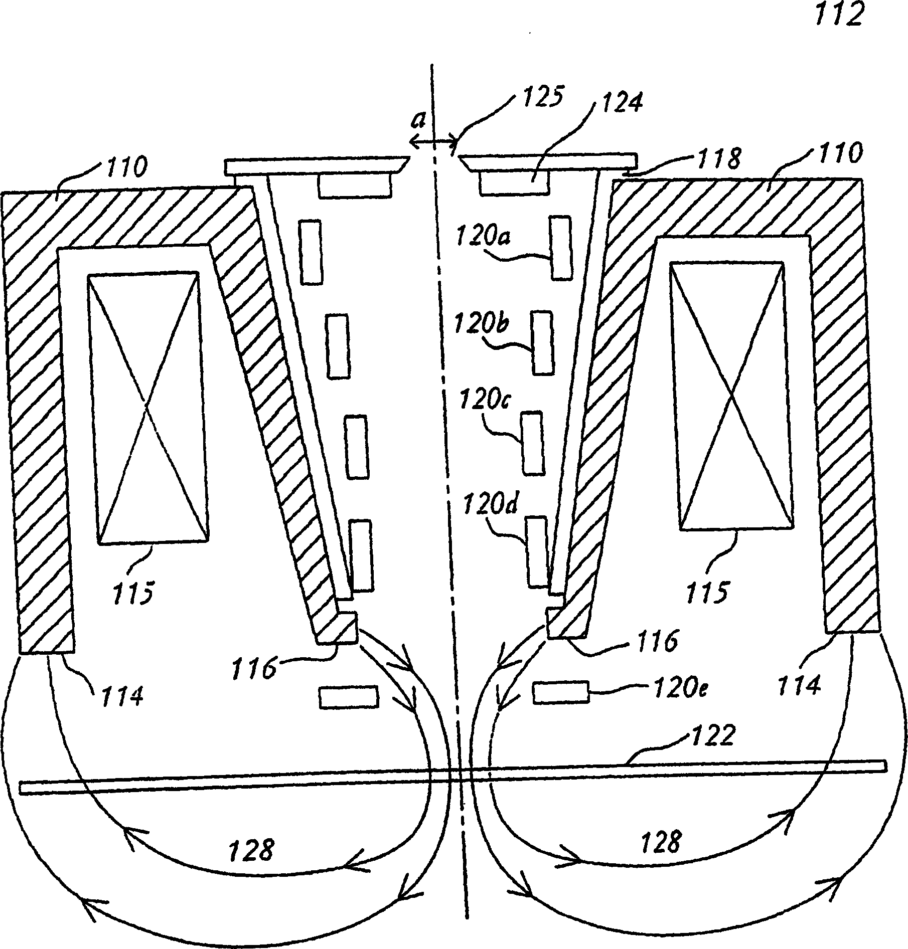
[0024] The magnetic lens includes a material 110 and an excitation coil 115 for providing magnetic power to a magnetic circuit with field lines passing through the magnetic material and between pole faces 116 and 114 . The central cavity of the magnetic lens has the shape of a circular bucket, which is axisymmetric with respect to the Z-axis. Where the primary par...


PUM

PropertyMeasurementUnit
Diameteraaaaaaaaaa

Abstract

A swinging objective retarding immersion lens system and method therefore which provide a low voltage electron beam with high beam current, relatively high spatial resolution, a relative large scan field, and high signal collection efficiency. The objective lens includes a magnetic lens for generating a magnetic field in the vicinity of the specimen to focus the particles of the particle beam on the specimen, an electrode having a potential for providing a retarding field to the particle beam near the specimen to reduce the energy of the particle beam when the beam collides with the specimen; a deflection system including a plurality of deflection units situated along the beam axis for deflecting the particle beam to allow scanning on the specimen with large area, at least one of the deflection units located in the retarding field of the beam, the remainder of the deflection units located within the central bore of the magnetic lens; and an annular detection unit with a relatively small aperture, located underneath the primary beam define aperture, to capture secondary electron (SE) and backscattered electrons (BSE).

Description

technical field [0001] The present invention generally relates to a scanning electron microscope, and in particular relates to a focusing and deflection system and method of a rotary deceleration submerged objective lens electron optics. range, and high signal capture efficiency. Background technique [0002] Scanning electron microscopes are used in many applications where the very small structures of objects need to be examined in great detail. Some of these applications include applications such as defect viewing and inspection of samples of very large scale integrated (VLSI) circuits, or chips, or other objects, the determination of detailed critical dimensions in these samples, and the design and processing of samples. Identification. Due to the short wavelength of the spot size generated for the scanning electron microscope, the location is generally about 0.2μm or less (1μm=10 -6 m) In the submicron scale, the scanning electron microscope is considered to be superi...

Claims


Application Information

Patent Timeline
IPC IPC(8): G01N23/00G21G5/00H01J3/14H01J3/26H01J37/141H01J37/28H01J47/00
CPCH01J37/141H01J37/28H01J2237/04756H01J2237/1035
Inventor Z·-W·陈
Owner ASML NETHERLANDS BV
Learn More