
Signal levelling detecting and dynamic tracking satellite antenna

A satellite antenna, dynamic detection technology, applied in the direction of antenna, non-electric variable control, electrical components, etc., can solve the problems of difficulty in normal operation of the system and high price

Inactive Publication Date: 2005-05-11
北京力峰天链通信技术有限公司
View PDF5 Cites 13 Cited by
  • Summary
  • Abstract
  • Description
  • Claims
  • Application Information

AI Technical Summary

Problems solved by technology

High-precision compasses are less expensive than high-precision inertial sensing devices, but they are also expensive
In addition, the compass is easily affected by changes in the magnetic field. If there is an abnormal magnetic field in the application, such as a magnetic field change caused by an electromagnetic device or a magnet, the system will not work properly.

Method used


Image

  • Signal levelling detecting and dynamic tracking satellite antenna

Examples


Embodiment 1

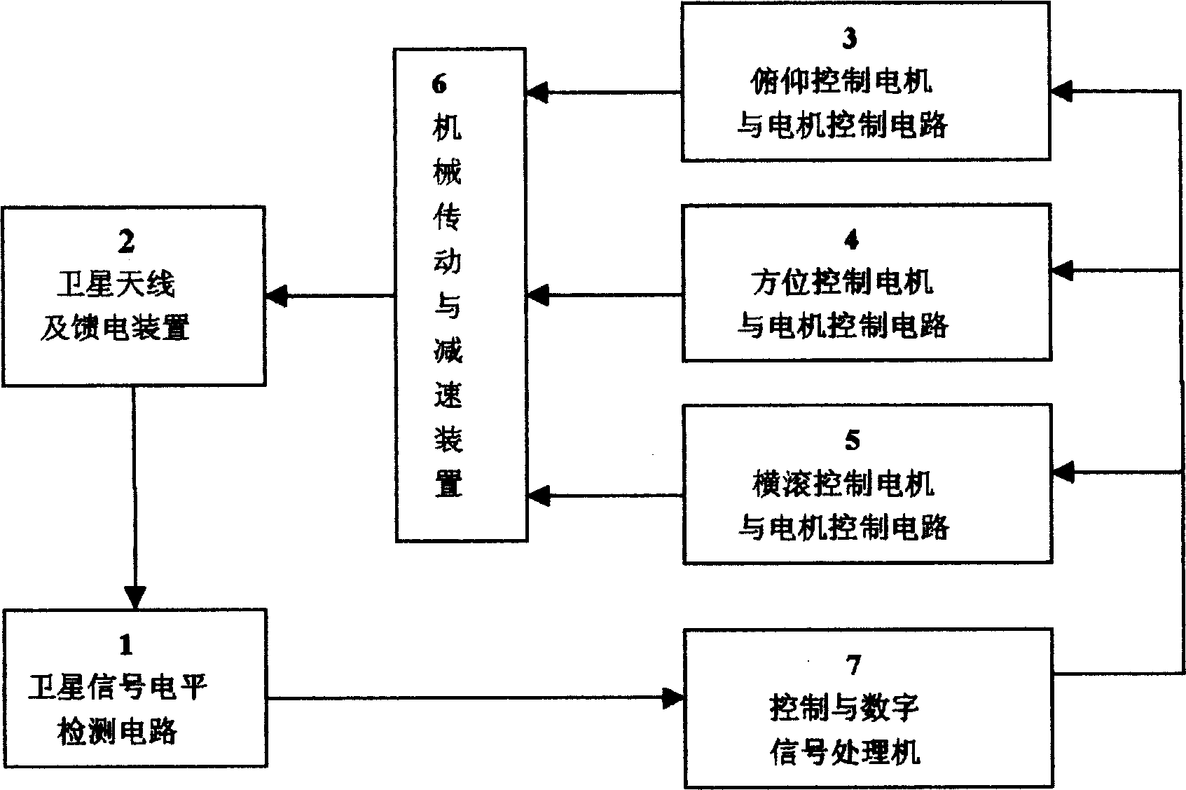
[0024] A typical two-axis (azimuth control and pitch control) satellite automatic tracking antenna system is implemented as follows:

[0025] Initial satellite search and alignment: After the system is turned on, the antenna is preset at a certain pitch angle, and the system starts to scan in a 360-degree direction, records the antenna position and the corresponding satellite signal strength, and searches for the position of the maximum satellite signal strength. If no satellite signal is found, change the pitch angle of the antenna, and re-search the 360-degree azimuth until the position of the maximum strength of the satellite signal is found, and then control the antenna to align with the satellite.

[0026] In addition, during the 360-degree azimuth scanning process of the antenna, through the signal processing computer, taking the signal strength e as a function, the derivative of the rotation angle θ of the antenna is calculated, and a mathematical method is used to dynam...

Embodiment 2

[0030] Similarly, the roll angle and pitch angle control parts can also be omitted at the same time to form a single-axis automatic tracking antenna system (at this time, the antenna should choose an antenna with a larger lobe width).


PUM


Abstract

The invention consists of level detection circuit of satellite signal, control and digital signal processor. The output of the control and digital signal processor is divided into three ways and each of them is connected with the pitch control motor and motor control circuit, the directional control motor and motor control circuit, roll control motor and motor control circuit. The other ends of three of them are connected with the level detection circuit of satellite antenna through mechanical drive and speed reduction.

Description

technical field [0001] The invention relates to a dynamic tracking satellite antenna, in particular to a satellite antenna which uses a satellite signal level detection method to realize dynamic tracking. Background technique [0002] So far, most of the dynamic automatic tracking satellite antenna systems rely on inertial platforms or high-precision gyroscope combinations to build a reference platform that does not physically rotate with the carrier. Such systems are as disclosed in Chinese patent application numbers 01104216, 94218035.6, 92231278.8 and 95190037.4. This type of system uses the satellite signal level as an auxiliary, but all adopts an angular velocity meter (a kind of gyro device) as the most important carrier rotation basis of measurement. The basic principle is: when the carrier moves, inertial sensor devices such as inertial platform, fiber optic gyroscope, electromechanical gyroscope and other components sense this movement, and convert it into a rotati...

Claims


Application Information

Patent Timeline
Patent Type & Authority Applications(China)
IPC IPC(8): G05D3/00H01Q3/02
Inventor 庞江帆
Owner 北京力峰天链通信技术有限公司
Learn More