
Optical coherence reflectometry with depth resolution

Active Publication Date: 2011-06-23
CARL ZEISS MEDITEC AG
View PDF19 Cites 33 Cited by
  • Summary
  • Abstract
  • Description
  • Claims
  • Application Information

AI Technical Summary

Benefits of technology

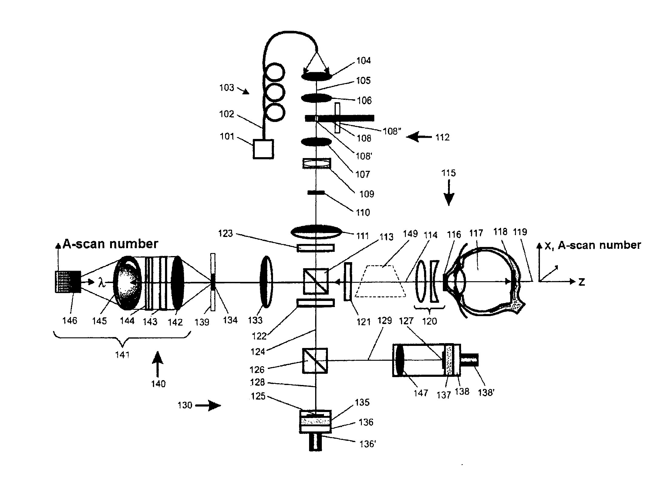
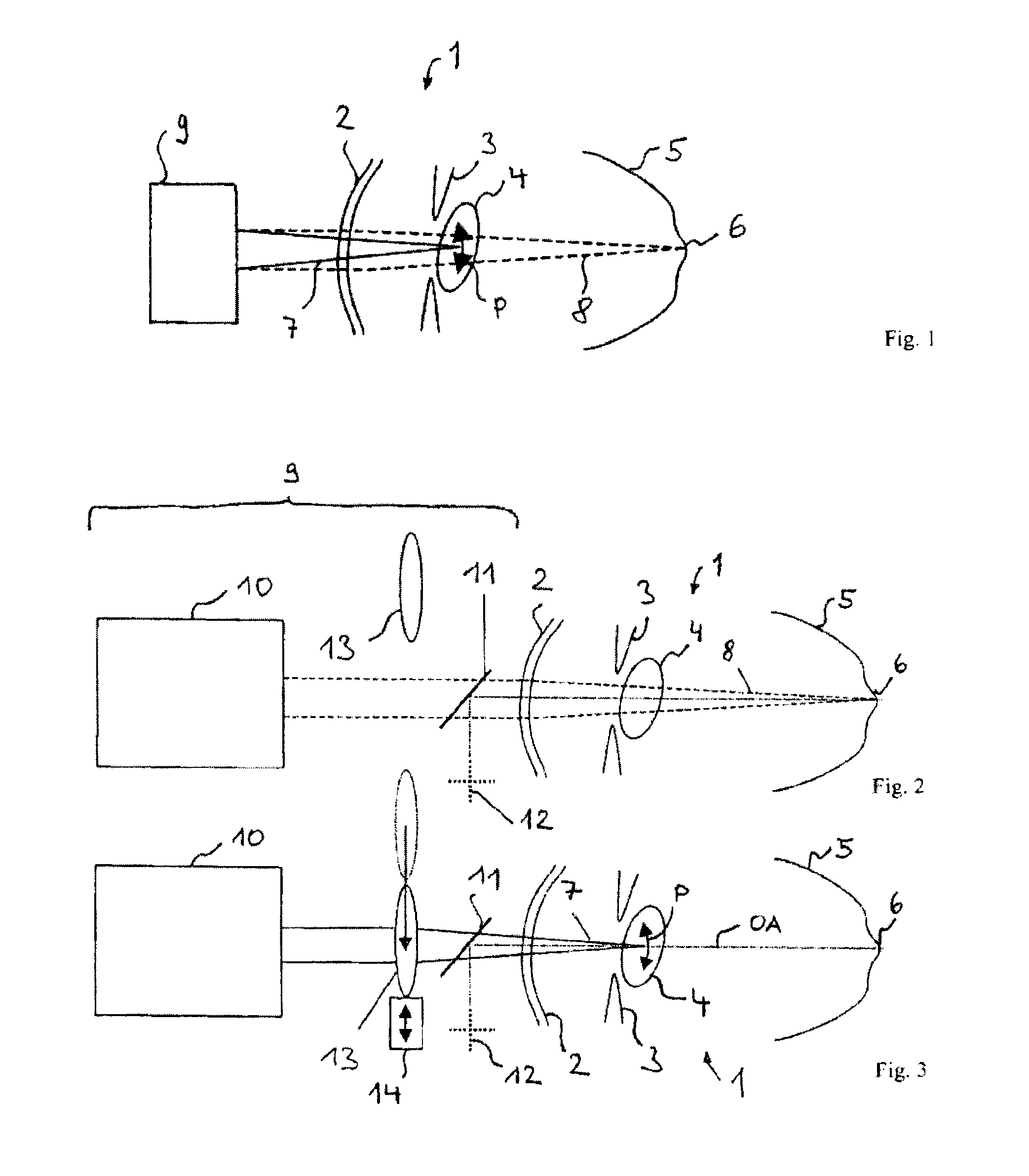
[0031]The invention is therefore based on the object of enabling an eye, and in particular a distance, to be measured in an improved manner by means of time-domain spectral domains or Fourier-domain coherence reflectometry. Particularly preferably, an axial length measurement and a further sub-full-distance measurement are to be performed on the eye at the same time. The signal-to-noise ratio and, in particular, the capacity for limiting-surface determination on the basis of volume scattering signals are to be improved, measurement errors are to be prevented and the requirements for adjustment of the eye are to be reduced.
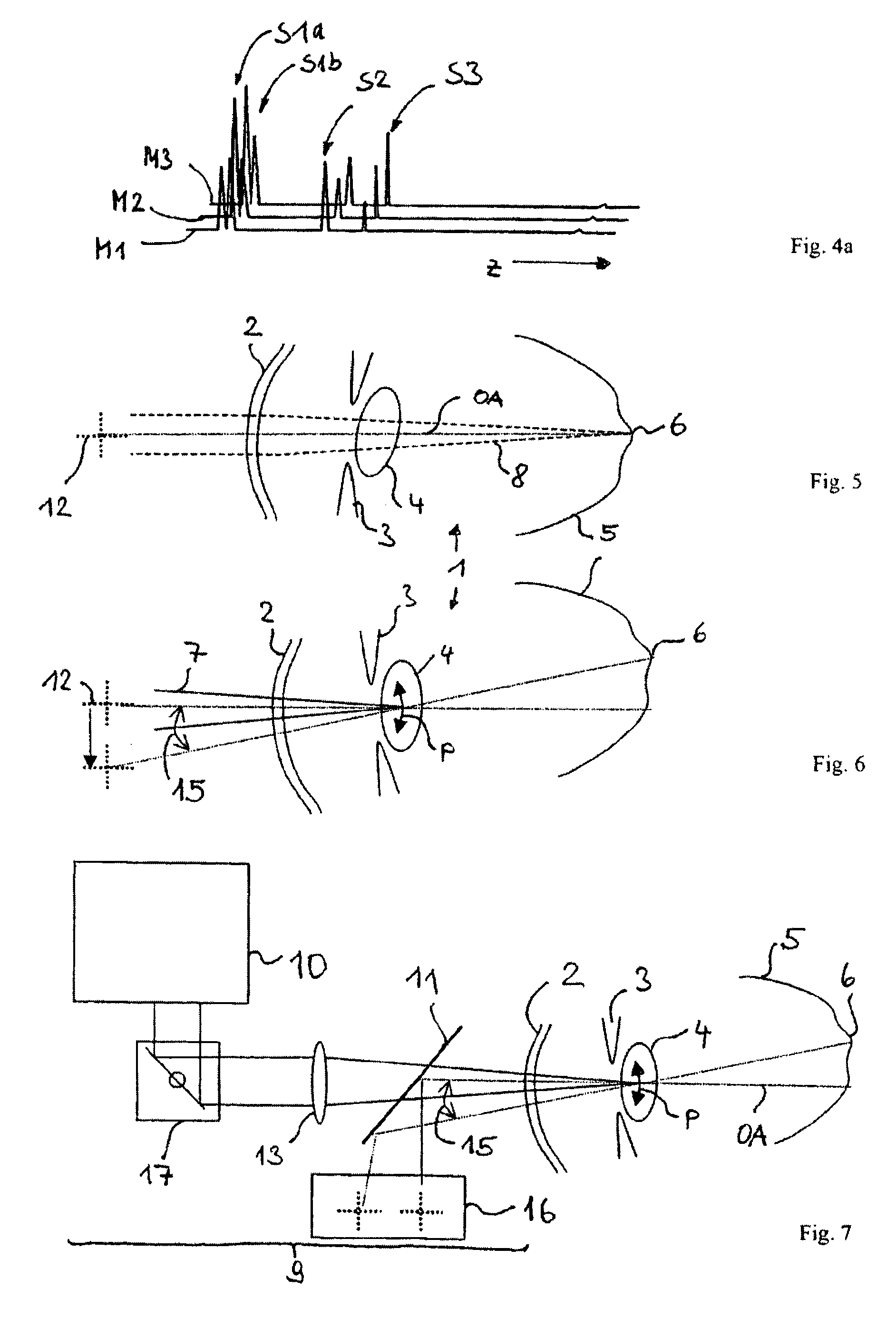
[0058]If the pairs of ascertained position of the anterior lens surface and ascertained position of the posterior lens surface are plotted on a diagram, wherein the position of the anterior lens surface is plotted along one diagram axis and the position of the posterior lens surface is plotted along the other diagram axis, combination or interpolation of the obtained points to form a curve makes it possible to determine a measurement for the tilt of the lens relative to the axis of vision, through evaluation of the maximum distance of the curve points from a symmetry axis of the curve.

Problems solved by technology

A problem for short coherence interferometry in the form of FD OCDR and FD OCT is the fixed association between the measurement region and the measurement resolution.

Method used


Image

  • Optical coherence reflectometry with depth resolution
  • Optical coherence reflectometry with depth resolution
  • Optical coherence reflectometry with depth resolution

Examples


Embodiment Construction

[0078]In the interferometric measurement of axial scatter profiles, such as that occurring in the case of optical coherence domain reflectometry, the axial resolution, i.e. the resolution in the depth direction, is given substantially by the coherence behaviour of the source. The resolution is inversely proportional to the total width of the spectrum used for measuring the scatter profile. Transversely in relation thereto, i.e. in the lateral direction, the achievable resolution is given by the lateral extent of the focus, which is referred to here as the focus diameter. In fact, of course, a beam waist is present, and the focus diameter is usually understood to be that size of the beam waist at which the radiation intensity has decreased to a particular value, e.g. 1 / e2.

[0079]The radiation back-scattered from a point on an object is the superposition of the radiation components back-scattered out of the resolved volume. These radiation components can interfere in all stages between...


PUM


Abstract

A device for performing distance measurements on an eye. The device includes an interferometer, focuses at least one measurement beam records backscattered radiation and interferometrically generates a measurement signal displaying structures of the eye by time-domain, spectral-domain or Fourier-domain coherence reflectometry, has an adjustment apparatus for laterally and / or axially displacing the focus in the eye or for varying a polarization state of the measurement beam and has a control apparatus which actuates the interferometer, wherein the control apparatus generates a plurality of A-scan individual signals from the backscattered radiation, combines these to an A-scan measurement signal and actuates the adjustment apparatus for displacing the position of the focus or for varying the polarization while recording the backscattered radiation from which the control apparatus generates the A-scan individual signals is being recorded.

Description

PRIORITY CLAIM[0001]The present application is a National Phase entry of PCT Application No. PCT / EP2009 / 005811, filed Aug. 11, 2009, which claims priority from Austrian Application Number A 1250 / 2008, filed Aug. 12, 2008, and German Application Number 102008051272.9, filed Oct. 10, 2008, the disclosures of which are hereby incorporated by reference herein in their entirety.FIELD OF THE INVENTION[0002]The invention relates to an apparatus for performing measurements on an eye, in particular for measuring ocular distances such as a depth of an anterior chamber, a lens thickness, a corneal thickness or an axial length, wherein the apparatus comprises an interferometer, focuses at least one measurement beam into the eye along an optical axis, collects back-scattered radiation and interferometrically generates a measurement signal indicating structures of the eye by time-domain, spectral-domain or Fourier-domain coherence reflectometry, and has an adjustment device for laterally and / or a...

Claims


Application Information

Patent Timeline
Patent Type & Authority Applications(United States)
IPC IPC(8): A61B3/117A61B3/10
CPCA61B3/1005
Inventor BARTH, ROLANDBERGNER, ROLANDBISSMANN, WILFRIEDVON BUENAU, RUDOLF MURAIHACKER, MARTINKOSCHMIEDER, INGOFERCHER, ADOLF FRIEDRICHGRAJCIAR, BRANISLAVEBERSBACH, RALF
Owner CARL ZEISS MEDITEC AG
Learn More