
Detection and Control of Power Induced Hop During Traction Control in a Vehicle

a technology of traction control and detection and control, which is applied in the direction of tractors, process and machine control, instruments, etc., can solve the problems of reducing the effect of traction control, and reducing the effect of torque adjustmen

Active Publication Date: 2009-04-30
FORD GLOBAL TECH LLC
View PDF37 Cites 33 Cited by
  • Summary
  • Abstract
  • Description
  • Claims
  • Application Information

AI Technical Summary

Benefits of technology

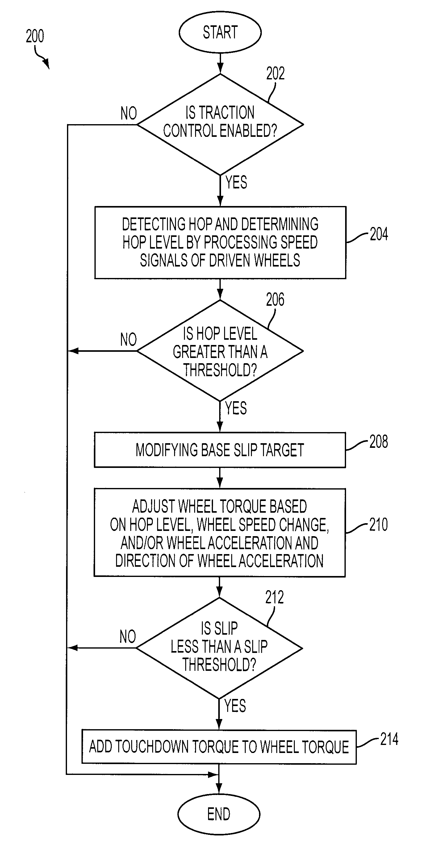
[0005]According to one aspect, a method for controlling a powertrain of a vehicle with wheels during a traction control event is provided. The method comprises adjusting wheel torque in response to an amplitude of a band-pass filtered driven wheel speed and a direction of acceleration of driven wheels. In one example, the amplitude of the band-pass filtered driven wheel speed provides an indication of hop, which can then be used to provide asymmetric torque control based on the direction of wheel acceleration. Specifically, by considering the direction of wheel acceleration, the torque control can reduce torque adjustments that contribute to the hop oscillation, and better damp the vibrations. In this way, it may be possible to utilize engine-based torque adjustments to reduce hop phenomenon effectively.
[0009]The methods described above may prevent or reduce power induced hop during traction control. For example, the methods may reduce the wheel torque adjustment as the hop level increases, even as the wheels decelerate. In this way, the wheel speed is encouraged to return to a slip level desired for reducing the hop. Thus, wheel hop may not be excited by the powertrain control system.

Problems solved by technology

However, the hop resonance may increase to a troublesome level on certain road surfaces.
As the suspension unloads the tire (for various reasons including surface roughness), water may be present between the road surface and tire, causing a loss of frictional torque capacity.
This cyclical interaction may excite the normally insignificant suspension vibration or hop resonance, and initiate significant oscillatory wheel acceleration, causing the wheels, or even the entire vehicle, to bounce.
However, the implementation of such actions may require a fast hop detecting or computing device and / or well-tuned, fast-acting, actuating components.
Consequently, it may be cost prohibitive for mass produced vehicles, such as those using traction control via engine torque reduction without brake actuation.

Method used


Image

  • Detection and Control of Power Induced Hop During Traction Control in a Vehicle
  • Detection and Control of Power Induced Hop During Traction Control in a Vehicle
  • Detection and Control of Power Induced Hop During Traction Control in a Vehicle

Examples


Embodiment Construction

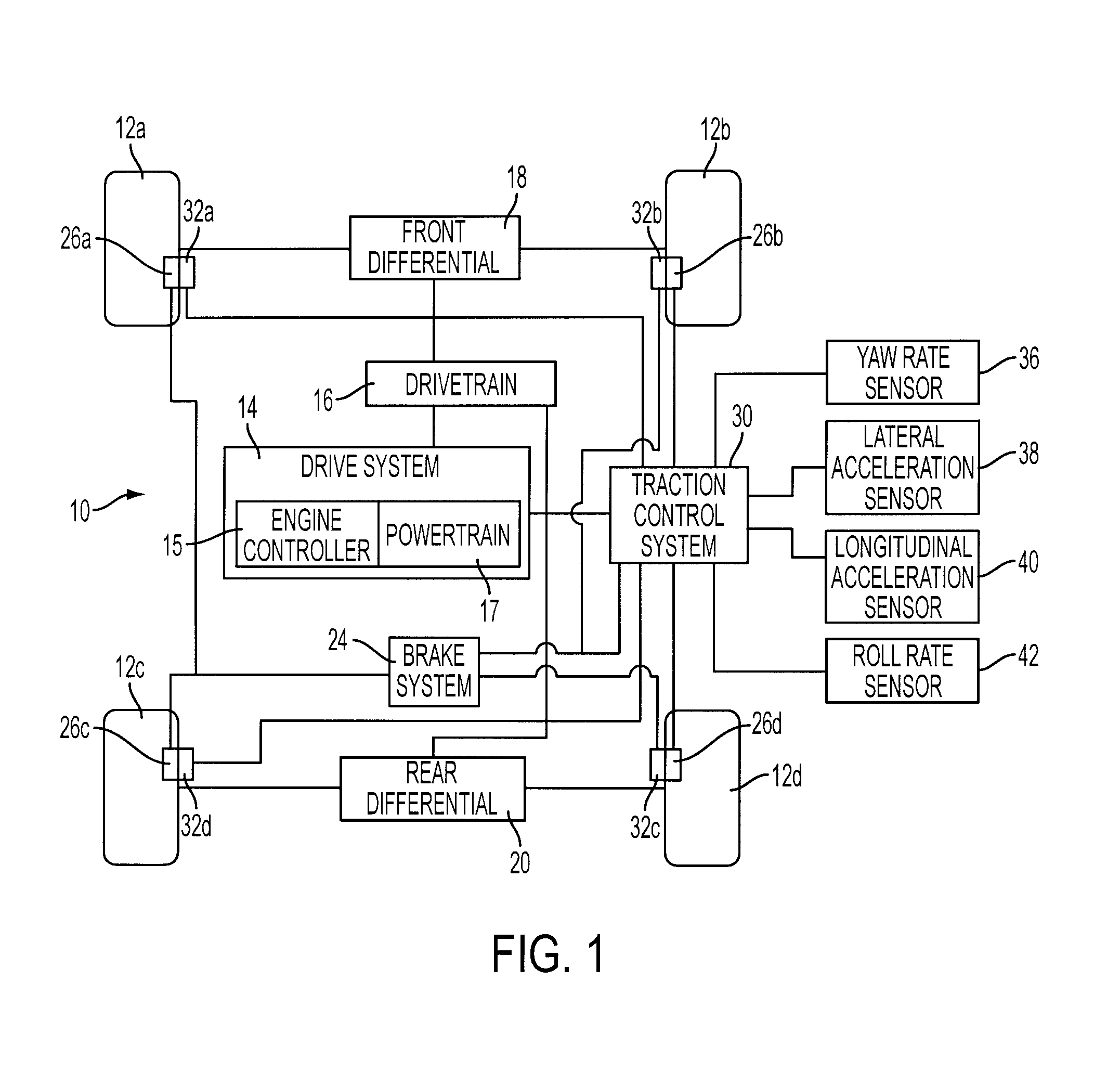
[0017]FIG. 1 is a block diagram of a vehicle 10 having a traction control system. As shown in FIG. 1, vehicle 10 may comprise wheel and tire assemblies 12a, 12b, 12c, and 12d. A drive system 14 coupled to a drivetrain 16 may provide power to the wheel and tire assemblies 12a-d through a front differential 18 and rear differential 20. Drive system 14 may include an engine controller 15 and a powertrain 17. Engine controller 15 may be a microprocessor-based system. Powertrain 17 may provide power by a power generating unit, such as an internal combustion engine, a hybrid electric system, an electric drive system, or a fuel cell system. Engine controller 15 may control the amount of torque and thus the amount of slip generated at each of the wheels. Drive system 14 may vary the amount of power output to effect a change in torque at wheel and tire assemblies 12a-d.

[0018]Drive system 14 may provide torque through drivetrain 16, which may include a transmission, front differential 18 and...


PUM


Abstract

A method for controlling a powertrain of a vehicle with wheels during a traction control event is provided. The method comprises adjusting wheel torque in response to an amplitude of a band-pass filtered driven wheel speed and a direction of acceleration of driven wheels.

Description

FIELD OF INVENTION[0001]The present application relates to the traction control of a vehicle, and more specifically, relates to mitigation of power induced hop during traction control.BACKGROUND[0002]In traction control operation, control of wheel slip on certain road surfaces may interact with natural frequencies in the driveline or suspension, which may be referred to as power induced “hop”. Hop resonances are caused by interactions between tire, road, and suspension components.[0003]On typical road surfaces, the transfer of engine power into vehicle acceleration and frictional losses at the tire keeps the amplitude of the hop resonance relatively low. However, the hop resonance may increase to a troublesome level on certain road surfaces. For example, on an asphalt surface with a thin layer of standing water, the friction coefficient (μ) and surface torque capacity may change significantly with respect to wheel slip and suspension loading. When a tire has full suspension force ac...

Claims


Application Information

Patent Timeline
IPC IPC(8): B60K28/16
CPCB60T8/175B60W30/18172B60W2520/105B60W2520/26B60W2520/14B60W2520/18B60W2520/125B60W2050/0052B60K28/16G05D17/02G05D19/02G05D19/00
Inventor LUEHRSEN, ERICFODOR, MICHAEL GLENNPERLICK, DONDUNN, DANIEL
Owner FORD GLOBAL TECH LLC
Learn More