Artificial crystalline lens with optical catalytic coating
A technology of artificial lens and crystalline lens, applied in the direction of intraocular lens, prosthesis, coating, etc., can solve the problem of no secondary cataract and other problems
- Summary
- Abstract
- Description
- Claims
- Application Information
AI Technical Summary
Problems solved by technology
Method used
Image

Examples
Embodiment 1
[0089] Example 1: Preparation of the artificial lens of the present invention
[0090] Place a silicone polymer with a diameter of 6 mm and a thickness of 1 mm in the reaction chamber of the vapor deposition machine. Then control the conditions of this reaction chamber to a pressure of 1×10 -4 To 5×10 -4 Torr, the temperature is between 200 to 300 degrees Celsius, and then 8KeV, 0.2A (1600W) electron beam is used to heat the titanium pentoxide in the tongs of the reaction furnace to evaporate. During the heating process, we set the partial pressure between 2×10 -5 To 10×10 -5 Torr oxygen is added into the reaction furnace to deposit photocatalytic titanium oxide on the surface of the silicone polymer to form a photocatalytic substance with a thickness of 100nm. The thickness of the photocatalytic titanium oxide It can be monitored by measuring the refractive index with an ellipsometer.
Embodiment 2
[0091] Example 2: Microbial culture
[0092] Culture of Escherichia coli
[0093] The microorganism used in the following examples is an E. coli strain (ATCC27325). E. coli (ATCC 27325) was inoculated into 100 ml of LB culture solution, and the culture solution was placed in an incubator with a temperature of 30° C. and a shaking rate of 200 rpm for shaking culture for 18 hours. After that, the culture solution was centrifuged at 7800xg for 15 minutes to collect E. coli cells, washed and resuspended in sterilized deionized water. The concentration of Escherichia coli bacteria liquid was determined by using a spectrophotometer (model: stronic 21 Milton Roy Co.) with a wavelength of 660 nm for turbidity measurement.
[0094] Lens epithelial cell culture
[0095] The epithelial cell line used in the following examples is the epithelial cell of human lens (ATCC CRL-11421; B3 cell). Human lens epithelial cells were placed and cultured in a petri dish at a temperature of 37°C, a humidit...
Embodiment 3
[0096] Example 3: Antimicrobial activity test of artificial lens
[0097] In this experiment, the artificial lens with photocatalytic substance coating prepared by the above method is used as a test to understand the antimicrobial ability of the artificial lens.
[0098] experimental method
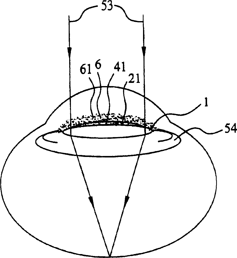
[0099] First, like Figure 5A As shown, there will be a TiO 2 The optical crystal body 2 (with a diameter of 6 mm) of the formed photocatalytic substance coating 41 is placed in a test plate with a well hole with an inner diameter of 6 mm. Next, add 0.5ml of 2×10 5 Pfu / ml E. coli bacteria liquid is put into each test well, and then the test plate is placed in an incubator with ultraviolet light for cultivation. Figure 5B It shows a case where an optical lens body 50 is placed in a well of a test dish and covered with a cell suspension 8 and then irradiated with UV light.
[0100] In this experiment, the ultraviolet light comes from a black tube (F40 / BL, Sylvania) with a wavelength of 375nm a...
PUM
| Property | Measurement | Unit |
|---|---|---|
| Thickness | aaaaa | aaaaa |
Abstract
Description
Claims
Application Information
 - R&D
- Intellectual Property
- Life Sciences
- Materials
- Tech Scout
- Unparalleled Data Quality
- Higher Quality Content
- 60% Fewer Hallucinations
Browse by: Latest US Patents, China's latest patents, Technical Efficacy Thesaurus, Application Domain, Technology Topic, Popular Technical Reports.
© 2025 PatSnap. All rights reserved.Legal|Privacy policy|Modern Slavery Act Transparency Statement|Sitemap|About US| Contact US: help@patsnap.com