
Rhombic carriage supporting steering mechanism

A steering mechanism, a diamond-like technology, applied in the field of vehicle engineering, can solve the problems that are not conducive to reducing the weight of the whole vehicle, occupy a large space, and are not very flexible in operation, and achieve a compact structure design, small space occupation, and weight reduction. Effect

Inactive Publication Date: 2005-03-23
HUNAN UNIV
View PDF1 Cites 3 Cited by
  • Summary
  • Abstract
  • Description
  • Claims
  • Application Information

AI Technical Summary

Problems solved by technology

The main models of automobiles are all four-wheeled automobiles with front engines. After years of development and improvement of automobiles with this structure, there is little room for further improvement in their safety and operational stability. The wheels are arranged in parallel, so the turning radius is relatively large, and the operation is not very flexible. At the same time, the chassis is a space-arranged structure, which has the defects of large space occupation and poor structural performance, which is not conducive to reducing the weight of the vehicle. , improve service life
The Chinese Patent Office has announced a kind of diamond-shaped automobile, (application number: 00128286.7), and its four wheels are arranged in a diamond shape by one front and rear and two in the middle. Relatively, the four-wheel automobile has a large change in structure and shape, but its The connection between the wheel and the frame still adopts the traditional overall connection method, and the connection between the front and rear wheels and the frame adopts a fork structure. Although the space occupied by the chassis is smaller than that of a four-wheeled vehicle, it still occupies a certain space. The transmission mode of rack and pinion is not convenient for the arrangement of other components

Method used


Image

  • Rhombic carriage supporting steering mechanism
  • Rhombic carriage supporting steering mechanism
  • Rhombic carriage supporting steering mechanism

Examples


Embodiment Construction

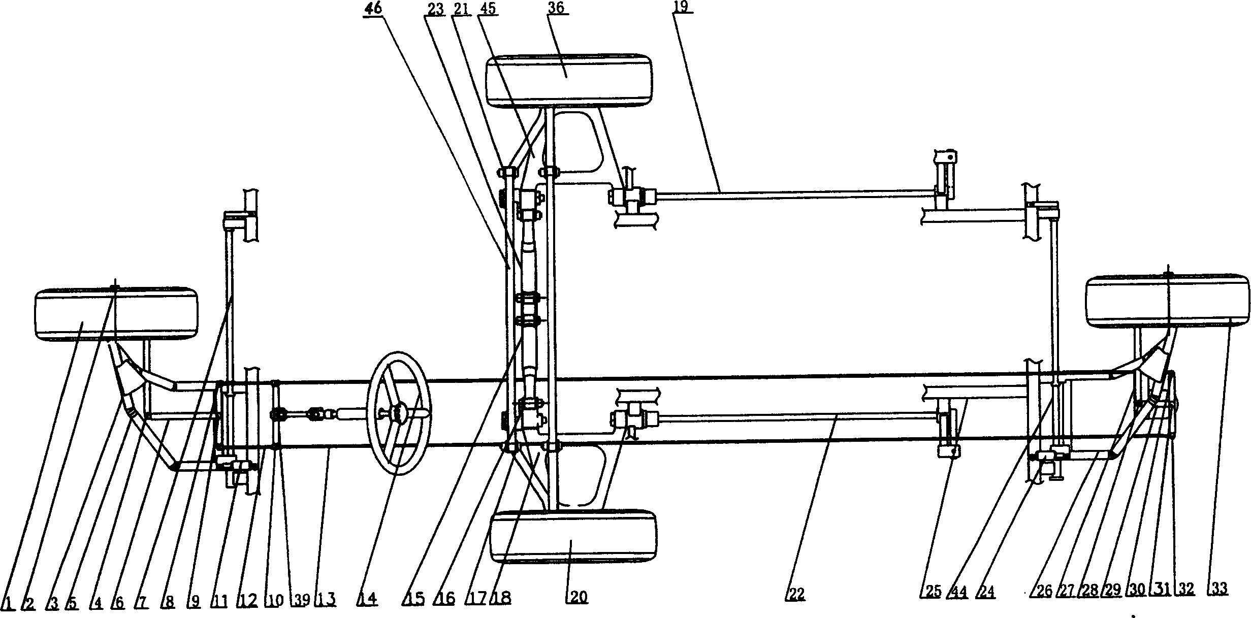
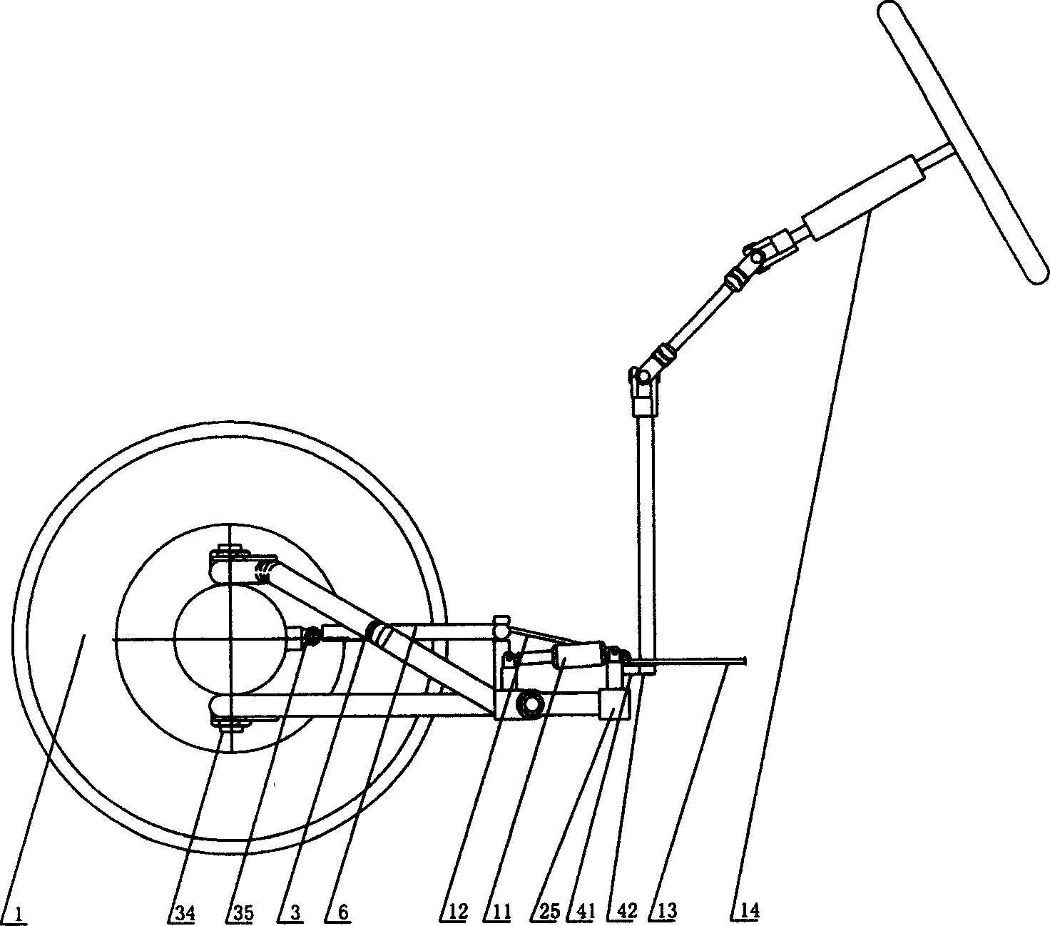
[0027] Such as figure 1 , figure 2 , image 3 As shown, the support of each wheel of the present invention is connected to the vehicle frame 25 independently through each suspension component respectively, like this, each member of chassis can be arranged on the same plane, to reduce the space occupied by chassis, wherein front wheel 1 and rear wheel 33 links to each other with vehicle frame 25 by front and rear suspension parts respectively, and left wheel 20 and right wheel 36 link to each other with vehicle frame 25 by intermediate suspension. The front and rear suspension components include trailing arms 3, 26 and torsion bar springs 7, 44, the front wheel 1 and the rear wheel 33 are respectively sleeved on the main shaft 2, and the kingpins 34, 37 are located at the front wheel 1 and the rear wheel respectively. 33 center plane, and perpendicular to the axis line of the main shaft 2, the front wheel 1 can be hinged with the longitudinal swing arm 3 through the kingpin ...


PUM


Abstract

This invention relates to a rhombic suspending and steering mechanism. Its suspending part consists of a front-rear suspending and a middle-suspending unit. The front-rear suspending unit consists of two longitudinal swing arms and torsion springs. The both longitudinal swing arms are respectively connected with front and rear wheel at their both ends, and connected with chassis via a torsion spring. The middle suspending unit consists of two lateral swing arms and torsion springs. The both lateral swing arms are respectively connected with one of side wheels at one of their ends, and connected with the chassis via a torsion spring. The steering part consists of a steering frame and a swing lever. The steering frame is connected with the front and rear wheels, and the swing lever, of which front portion is equipped with a large gear wheel engaged with a small gear wheel that is connected with the steering wheel. The front wheel and rear wheel are located on a lnogitudinal line. The suspending mechanism occupies space less and can turn in a short radius. It has a bumping effect due to its front suspending unit when a collision occurs.

Description

Technical field: [0001] The invention relates to the field of vehicle engineering, in particular to a support and steering mechanism for a diamond-shaped vehicle chassis. Background technique: [0002] At present, automobiles are mainly classified into three-wheeled vehicles and four-wheeled vehicles according to the layout of the wheels. Among them, three-wheeled vehicles are equipped with a single wheel on the front axle, left and right wheels are installed on the rear axle, and four-wheeled vehicles are equipped with front and rear wheels. Each axle is equipped with left and right wheels, and the engine of the car adopts two modes of front and rear. The main models of automobiles are all four-wheeled automobiles with front engines. After years of development and improvement of automobiles with this structure, there is little room for further improvement in their safety and operational stability. The wheels are arranged in parallel, so the turning radius is relatively lar...

Claims


Application Information

Patent Timeline
Patent Type & Authority Applications(China)
IPC IPC(8): B62D61/00
Inventor 钟志华
Owner HUNAN UNIV
Learn More