
Automatic correcting frequency method for time-division radio communication system and apparatus thereof

An automatic frequency correction and wireless communication system technology, applied in time division multiplexing systems, transmission systems, synchronization devices, etc., can solve problems such as poor performance, dynamic adjustment, and impact

Active Publication Date: 2005-02-09
XUANPU INDUSTRY CO LTD
View PDF4 Cites 35 Cited by
  • Summary
  • Abstract
  • Description
  • Claims
  • Application Information

AI Technical Summary

Problems solved by technology

For example, in U.S. Patent 2003099206, the title of the invention is "Method and Arrangement for Automatic Frequency Correction" (Method and Arrangement for Automatic Frequency Correction), a frequency correction method in UTRA TDD mode is disclosed, but only the strongest propagation path is used to Perform frequency offset estimation and use a fixed AFC loop gain factor at the same time, so the performance will be affected to a certain extent in the case of fast fading and multiple strong propagation paths, and its correction accuracy is also very limited
[0015] (3) Although the partial automatic frequency correction method also divides AFC into several stages, and uses different AFC loop gain factors in each stage to control the convergence and tracking performance of AFC in different stages, the AFC stage switching is often through some kind of convergent judgment
However, in these schemes, due to the inaccuracy of the convergence judgment, or because it takes a long time to obtain a more accurate convergence judgment, it often takes a long time to reach the AFC loop under low signal-to-noise ratio conditions. the convergence
On the other hand, since the relevant AFC parameters in these methods are generally preset and cannot be dynamically adjusted according to actual channel conditions, the performance may be poor in some communication environments

Method used


Image

  • Automatic correcting frequency method for time-division radio communication system and apparatus thereof
  • Automatic correcting frequency method for time-division radio communication system and apparatus thereof
  • Automatic correcting frequency method for time-division radio communication system and apparatus thereof

Examples


Embodiment Construction

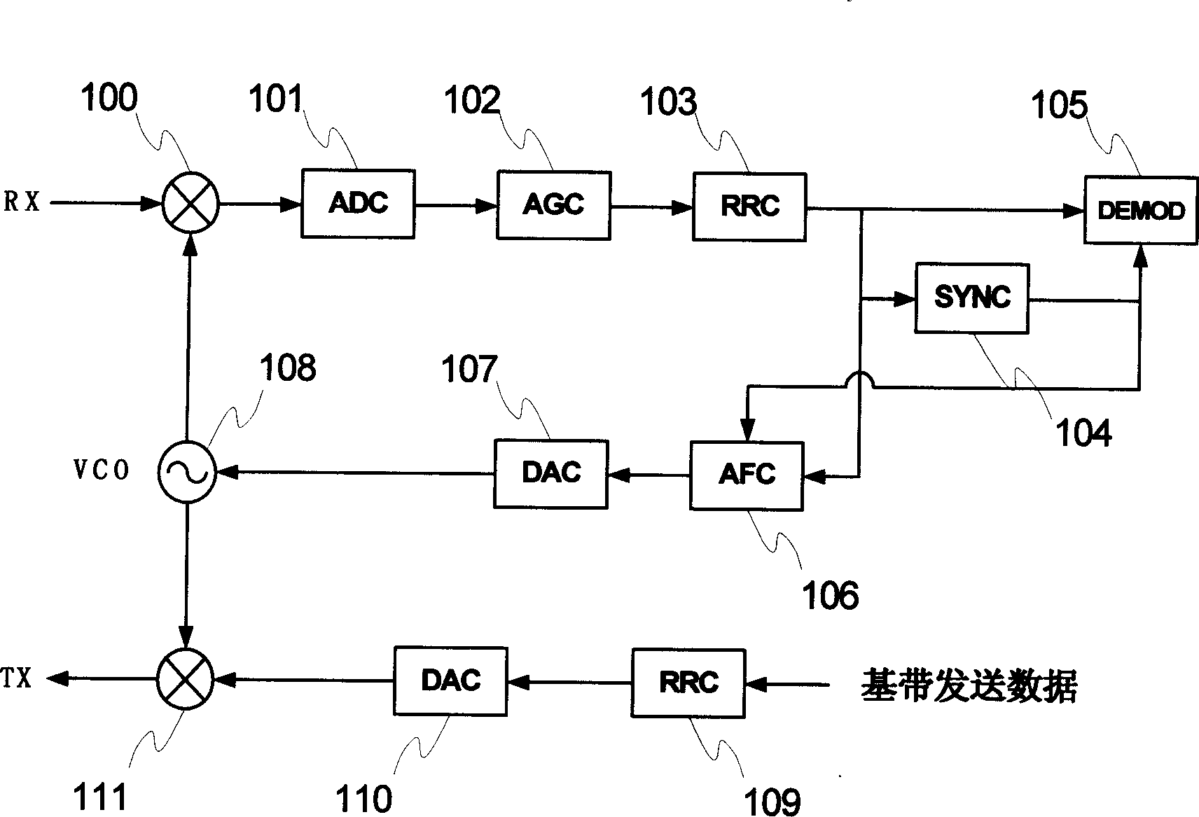
[0100] FIG. 1 shows a block diagram of a conventional digital transceiver in the prior art. Referring to Fig. 1, the received radio frequency signal is down-converted into an analog baseband signal by a mixer (Mixer) 100, and then passed through an analog-to-digital converter (ADC) 101, an automatic gain controller (AGC) 102 and an RRC filter 103 to obtain a digital baseband signal Signal. Through a series of digital signal processing, the synchronization module 104 obtains synchronization information, including frame synchronization and system synchronization information. After the synchronization is established, the demodulator 105 performs processing such as despreading and demodulation to restore the transmission information. On the other hand, the transmitted information passes through an RRC shaping filter 109 , a digital-to-analog converter (DAC) 110 , and is up-converted by a mixer 111 to obtain a transmitted radio frequency signal.

[0101] In the structural block d...


PUM


Abstract

The automatic frequency correction method and device includes two stages of coarse frequency correction and fine frequency correction. The coarse frequency correction includes the steps of signal extraction, sliding correlation and phase deviation estimation, multiple frequency merging, creating time delay envelope, route selection, multipath merging, frequency control, etc. and corresponding modules. The fine frequency correction includes the steps of signal extraction, channel estimation and route search, route merging, frequency deviation estimation, SINR estimation, Kalman gain factor calculation, the first order loop filtering, frequency control, etc. and corresponding modules. The present invention makes it possible for the receiver to realize frequency sync in time division system fast accurately in harsh mobile communication environment.

Description

technical field [0001] The present invention generally relates to wireless communication systems, and in particular to an automatic frequency correction (Automatic Frequency Correction, AFC for short) method and device for a time division (Time Division) wireless communication system receiver. Background technique [0002] In a typical wireless communication system, due to the frequency deviation between the local oscillator (Local Oscillator) of the transmitter and the receiver, it can lead to serious degradation of received signal quality, and even failure of communication transmission. In particular, for the User Equipment (UE) in the cellular mobile communication system, due to economic considerations, etc., a local oscillator with low frequency stability is often used, and its initial frequency offset (Initial Frequency Offset) can reach About 10ppm, this is equivalent to an initial frequency deviation of about 20kHz for a system using a 2GHz carrier. If corresponding ...

Claims


Application Information

Patent Timeline
IPC IPC(8): H04B1/707H04B7/26H04J3/06H04L7/00H04L25/03
Inventor 谢一宁刘栋李煊
Owner XUANPU INDUSTRY CO LTD
Learn More