
Method of using global magnetic field as energy source and micro energy power machine and micro energy self supply generating set

A technology of the earth's magnetic field and power machine, applied in the direction of generators/motors, electromechanical devices, electrical components, etc., can solve environmental problems such as pollution and large fuel consumption, and achieve the effects of energy saving, light weight, and convenient transportation

Inactive Publication Date: 2004-07-21
马健 +2
View PDF0 Cites 0 Cited by
  • Summary
  • Abstract
  • Description
  • Claims
  • Application Information

AI Technical Summary

Problems solved by technology

[0003] In order to overcome the shortcomings of existing power engines (steam engines, internal combustion engines, diesel engines, nuclear power engines) that consume a large amount of fuel and cause serious pollution to the environment, the present invention provides a method for utilizing the energy of the earth's magnetic field and equipment for utilizing the energy of the earth's magnetic field

Method used


Image

  • Method of using global magnetic field as energy source and micro energy power machine and  micro energy self supply generating set
  • Method of using global magnetic field as energy source and micro energy power machine and  micro energy self supply generating set
  • Method of using global magnetic field as energy source and micro energy power machine and  micro energy self supply generating set

Examples


Embodiment Construction

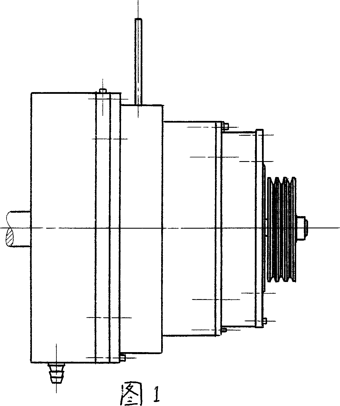
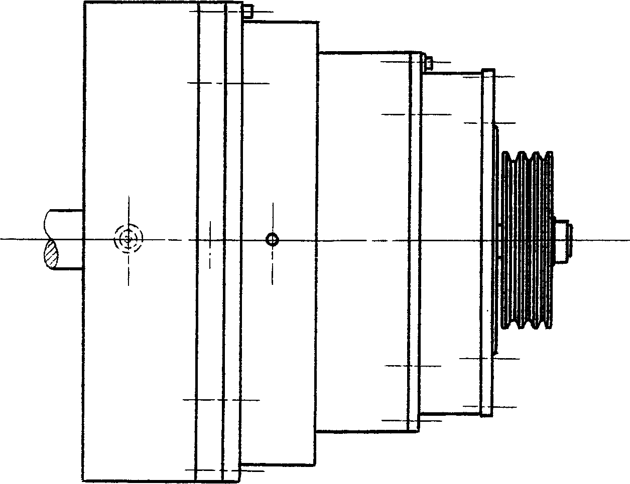
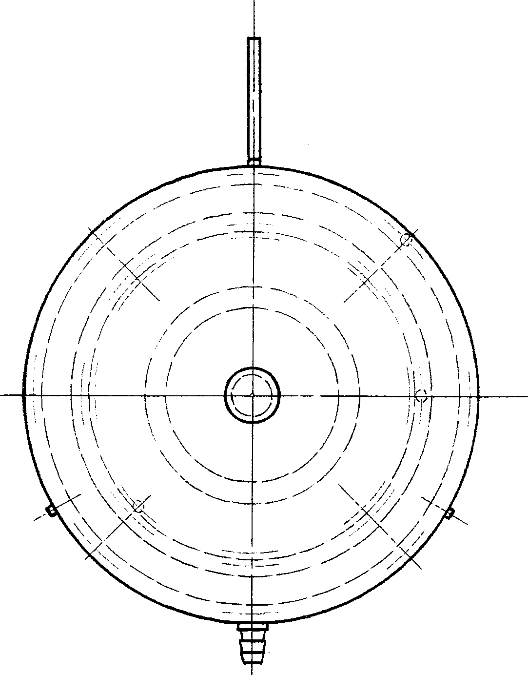
[0028] In Figure 1, figure 2 and image 3 Among them, the appearance of the micro-energy power machine of the present invention is conch-shaped.

[0029] exist Figure 4 and Figure 5 Among them, the large housing 27 is in the shape of a dome, and there is a large round through hole in the middle of the top of the cover; two small through holes are arranged on the wall;

[0030] exist Image 6 and Figure 7 Among them, the planet carrier body 28 is in the shape of a gear (but without teeth), with a shaft hole in the middle; there are three circles between the shaft hole and the outer wall, and round holes are evenly distributed, and the inner ring has 3 holes; the middle ring has 8 holes , 4 of which are bearing seat holes, 4 are straight through holes for counterweights; 8 bolt holes are used in the outer ring.

[0031] exist Figure 8 and Figure 9 Among them, the inner ring gear 31 is in the shape of an enamel ring, and the inner wall is evenly distributed with gear...


PUM


Abstract

The invention overcomes disadvantages of current power machine in consuming a great lot fuel and causing environmental pollution. Movement of speeding up in three stages and speeding down in one stage makes micro energy power machine become a non-linear system quickly, entering into attractor region and strange attractor region of earths magnetic field, where the power machine is coupled to earths magnetic field to generate electron magnetic resonance. Locking up electromagnetism frequency, i.e. positioning coupling point as well as absorbing and correcting energy in earths magnetic field effectively in good time generate spin of the power machine so as to output power endlessly and realize controllable 'racing effect'.

Description

[technical field] [0001] The invention provides a method for using the earth's magnetic field as an energy source and a device for using the earth's magnetic field as an energy source. [Background technique] [0002] At present, known power machine is made up of body, cylinder, crankshaft etc., is fuel with gasoline, diesel oil or natural gas, generates power by ignition, exhaust, explosion work. The general power machine is not only bulky, but also consumes a lot of steel and fuel. These fuels are limited, and the waste gas generated after combustion causes serious pollution to the environment. [Content of the invention] [0003] In order to overcome the shortcomings of existing power engines (steam engines, internal combustion engines, diesel engines, nuclear power engines) that consume a large amount of fuel and cause serious pollution to the environment, the present invention provides a method for utilizing the energy of the earth's magnetic field and equipment for ut...

Claims


Application Information

Patent Timeline
Patent Type & Authority Applications(China)
IPC IPC(8): H02K53/00H02N11/00
Inventor 马健熊万林伍康旺
Owner 马健
Learn More