Optical recording medium
A technology of optical recording medium and recording film, which is applied in the direction of optical recording carrier, optical recording system, data recording, etc., can solve the problems of insufficient research on groove side wall optimization, steepness, slope of groove side wall, etc., and achieve excellent Reproduction characteristics, effects of high reproduction output
- Summary
- Abstract
- Description
- Claims
- Application Information
AI Technical Summary
Problems solved by technology
Method used
Image

Examples
no. 1 example
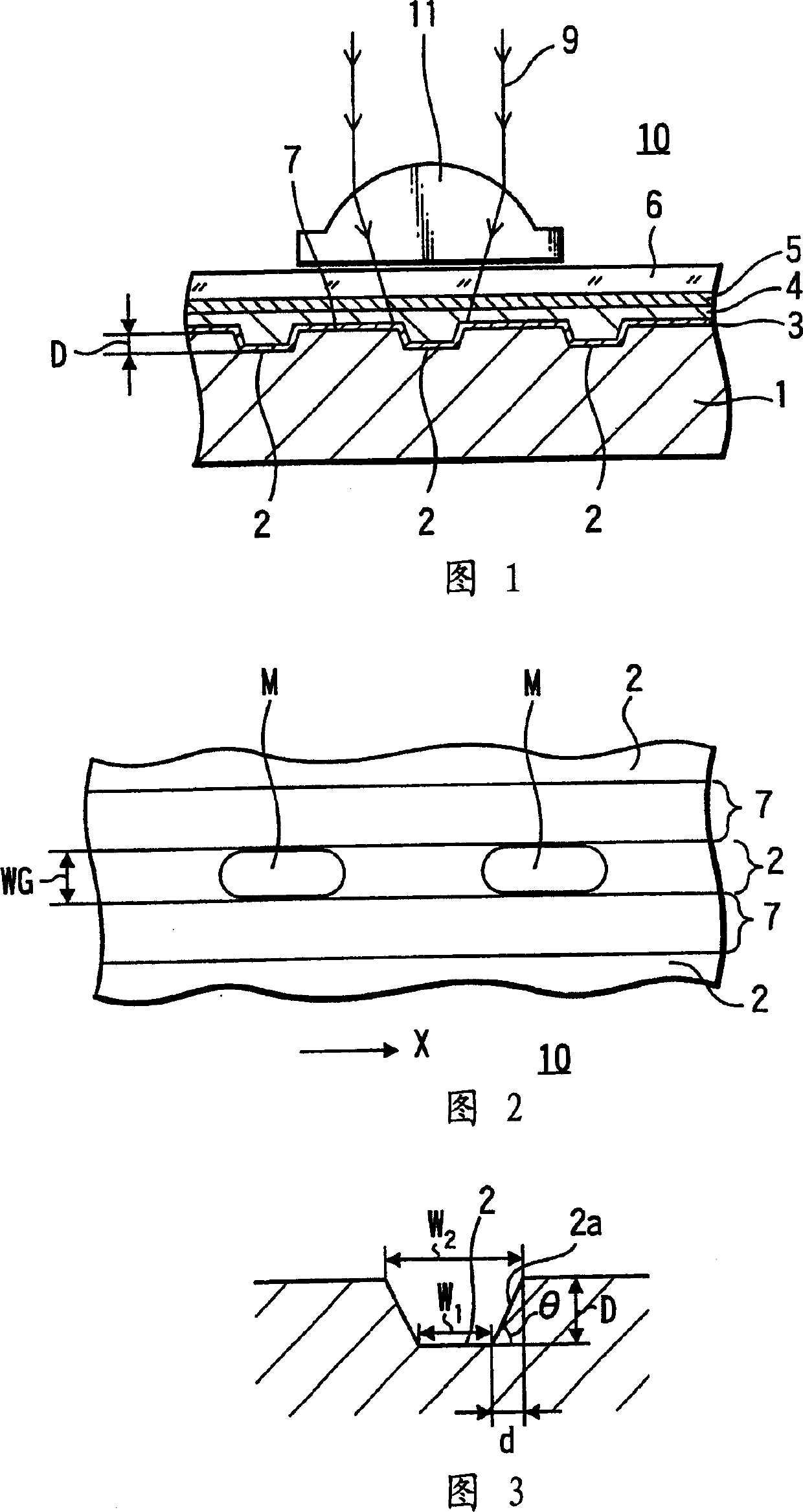
[0071] In this embodiment, the concave portion 2 is a groove arranged as a tracking guide groove, the size of which is 100 nm deep, 0.12 μm wide, and the interval between the grooves is 0.6 μm, and the slope of the side wall of the groove is tanθ =2, as shown in Figure 3.
[0072] Also, in this embodiment, a phase modulation type optical disc is produced using a polycarbonate (PC) substrate 1 in which a depressed portion 2, i.e., a groove, is formed on one main surface of the substrate 1, and a metal film 3 was formed by sputtering Ag to a thickness of 20 nm on the groove-forming surface, and a recording film 4 of an organic pigment film, a dielectric film 5 formed of SiN with a thickness of 10 nm, and a light-transmitting protective film 6 were sequentially formed on the metal film 3.
[0073] Organic pigment films are formed by spin coating. In this case, the thickness of the film was set to be 170 nm inside the groove and 70 nm at the land portion.
[0074] In addition, i...
no. 2 example
[0084]FIG. 8 shows the measurement results of the corresponding reproduced signal amplitude, that is, the amount of returning light obtained by changing the groove width in the optical recording medium according to the first embodiment. As shown in FIG. 8, the signal amplitude decreases when the groove width exceeds a certain value. The reason for this is that when the groove width is thus increased compared to the mark width, the ratio of the mark width within the reproducing spot increases as the reproducing spot approaches the center of the mark, and the reflectance due to the difference with the land portion Interference is reduced and increased.
[0085] Specifically, FIG. 9 shows reproduced signal levels in the groove length direction when the groove width is increased to 0.28 µm. According to FIG. 9, the reflectance increases near the center of the mark.
[0086] According to FIG. 8 , it can be understood that the best results can be obtained when the groove width is ...
no. 3 example
[0093] In the third embodiment, similarly to the first embodiment, a phase modulation type optical disc is manufactured by using a substrate 1 utilizing polycarbonate (PC), in which grooves are formed as depressed portions 2, and side walls are substantially vertical The metal film 3 is formed by sputtering 20nm thick Ag on the surface where the groove is formed, and then a recording film 4 formed of an organic pigment film, a dielectric film 5 formed of 10nm thick SiN, and an optical film are deposited thereon. Transmission protective film 6.
[0094] Regarding the width of the groove of the recessed portion 2 in the substrate, in order to obtain the above-mentioned excellent effect, in this embodiment, the width of the recessed portion 2, that is, the width of the groove is set to 0.14 μm. In addition, the width of the land is set to be the same as the width of the groove. N.A. of the objective lens = 0.85.
[0095] Furthermore, in this embodiment, an optical disk is manuf...
PUM
| Property | Measurement | Unit |
|---|---|---|
| wavelength | aaaaa | aaaaa |
| reflectivity | aaaaa | aaaaa |
| reflectivity | aaaaa | aaaaa |
Abstract
Description
Claims
Application Information
 - R&D
- Intellectual Property
- Life Sciences
- Materials
- Tech Scout
- Unparalleled Data Quality
- Higher Quality Content
- 60% Fewer Hallucinations
Browse by: Latest US Patents, China's latest patents, Technical Efficacy Thesaurus, Application Domain, Technology Topic, Popular Technical Reports.
© 2025 PatSnap. All rights reserved.Legal|Privacy policy|Modern Slavery Act Transparency Statement|Sitemap|About US| Contact US: help@patsnap.com