
Tuning fork type piezoelectic oscillatory sheet, its mfg. method and piezoelectric device

A tuning-fork type piezoelectric and piezoelectric oscillation technology, which is applied in the manufacturing/assembly of piezoelectric/electrostrictive/magnetostrictive devices, piezoelectric devices/electrostrictive devices, and piezoelectric/electrostrictive devices, etc. It can solve problems such as the increase of natural frequency fluctuation value, the decrease of piezoelectric oscillator plate, and the unstable vibration characteristics.

Inactive Publication Date: 2003-10-08
SEIKO EPSON CORP
View PDF3 Cites 19 Cited by
  • Summary
  • Abstract
  • Description
  • Claims
  • Application Information

AI Technical Summary

Problems solved by technology

As a result, there is a risk of unstable vibration characteristics due to distortion energy loss due to vibration leakage
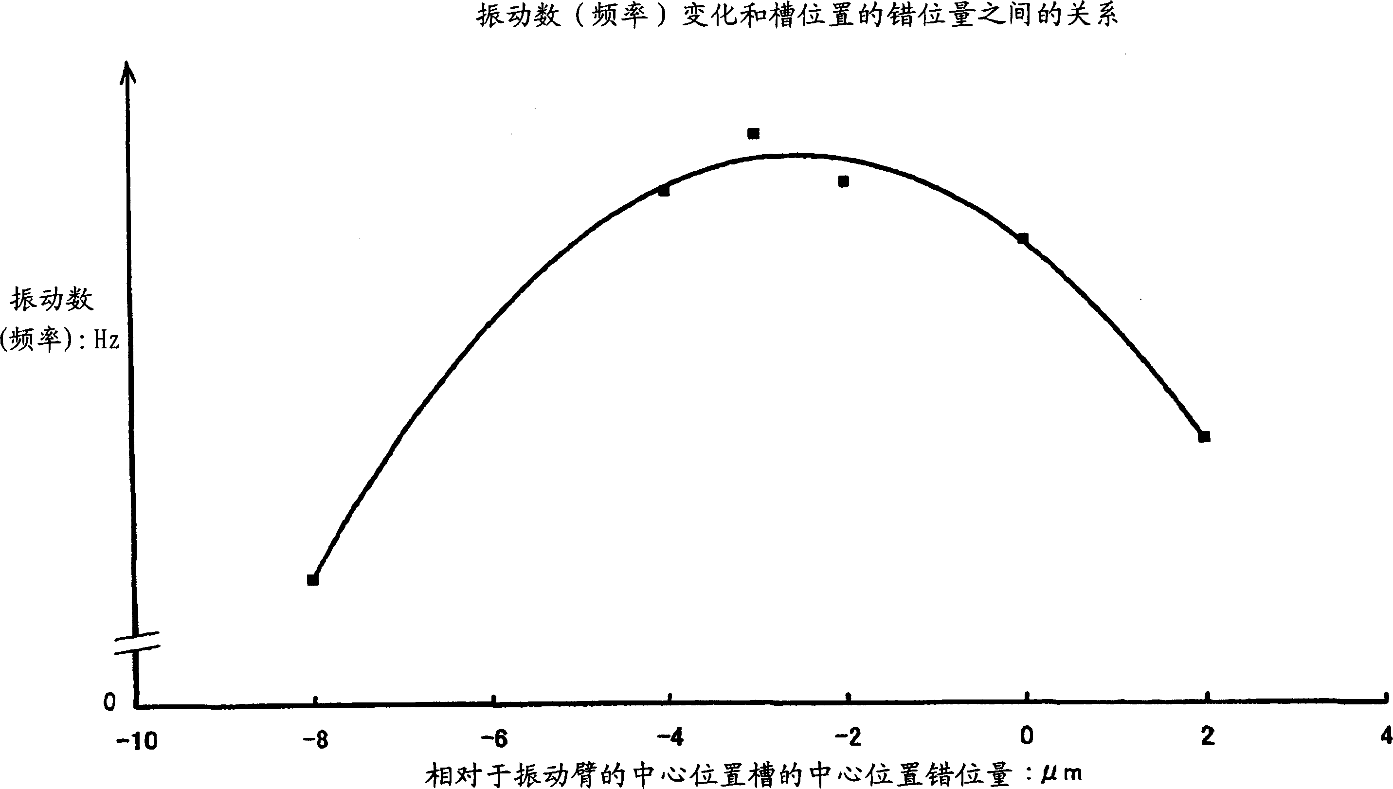
In addition, if this distortion energy loss increases, there is a problem that the natural frequency of the piezoelectric vibrating piece, that is, the number of resonant frequencies decreases, and the fluctuation value of the natural frequency increases.

Method used


Image

  • Tuning fork type piezoelectic oscillatory sheet, its mfg. method and piezoelectric device
  • Tuning fork type piezoelectic oscillatory sheet, its mfg. method and piezoelectric device
  • Tuning fork type piezoelectic oscillatory sheet, its mfg. method and piezoelectric device

Examples


Embodiment Construction

[0054] Hereinafter, preferred embodiments of the present invention will be described in detail with reference to the accompanying drawings.

[0055] figure 1 A preferred embodiment of a crystal oscillator suitable for the present invention is schematically shown.

[0056] Such a crystal resonator 10 includes a package 13 having a base 11 and a cover 12 made of an insulating material, and a tuning-fork-shaped crystal oscillator piece 14 is hermetically packaged inside the package 13 . The base 11 has a substantially rectangular box shape in which a plurality of thin ceramic plates are laminated, and a tuning-fork-shaped crystal resonator piece 14 is attached to the bottom of a space defined inside. The cover 12 is formed of a rectangular thin plate made of an insulating material such as glass or ceramics, and is hermetically connected to the upper end surface of the base 11 by low-melting glass. In order to adjust the frequency to be able to irradiate the laser beam from the...


PUM


Abstract

The tuning fork type crystal vibrating piece (14) is constituted like this, by wet etching the Y axis of its crystal axis, the X axis and the Z axis correspond to the length direction, the width direction and the thickness direction of the vibrating arms (16a), (16b) For the oriented crystal substrate, grooves (18a) and (18b) in the longitudinal direction are arranged on the main plane of the vibrating arm. , the left and right stiffnesses in the width direction of the vibrating arm are balanced, and the bending motion of the vibrating arm is stabilized. In the manufacturing process of the tuning fork type piezoelectric vibrating plate, the dislocation of the position in the width direction of the upper and lower main planes (17a) and (17b) of the vibrating arm caused by the misalignment of the photomask, on the cross section in the width direction of the vibrating arm, in the thickness direction The centers of gravity M1 and M2 of the upper and lower parts divided into two equal parts are adjusted on the same straight line perpendicular to the main plane. By adjusting the relative positions of the grooves (18a) and (18b) in the width direction, vibration due to vibration Displacement in the thickness direction of the arm is eliminated and suppressed, and distortion energy loss due to vibration leakage is prevented. High stability is achieved by suppressing the CI value to improve its performance.

Description

technical field [0001] The present invention relates to piezoelectric devices such as piezoelectric vibrators and piezoelectric oscillators used in various electronic devices, piezoelectric vibrating gyroscopes used in angular velocity sensors, and more specifically, to tuning fork-type piezoelectric devices used in this regard. Oscillating plate and its manufacturing method. Background technique [0002] For a long time, in ordinary clocks and household appliances, various information, communication instruments and OA instruments and other civil and industrial electronic instruments, piezoelectric vibrators, piezoelectric oscillators and Piezoelectric devices such as oscillators and real-time clock modules in which IC chips are packaged in the same package. In addition, piezoelectric vibrating gyroscopes are widely used as rotation angular velocity sensors for attitude control and navigation control of ships, aircraft, and automobiles, and for preventing and detecting hand...

Claims


Application Information

Patent Timeline
IPC IPC(8): G01C19/56G01C19/5621G01C19/5628H01L41/09H01L41/22H01L41/29H01L41/332H03H3/02H03H3/04H03H9/19H03H9/215
CPCG01C19/5607H03H3/04H03H9/215H03H2003/0492Y10T29/42
Inventor 菊岛正幸
Owner SEIKO EPSON CORP
Learn More