
Measuring device for contactlessly detecting ferromagnetic object

A measuring device, non-contact technology, applied in measuring devices, using electric/magnetic devices to transfer sensing components, converting sensor output, etc., to achieve the effect of simple structure and high precision

Inactive Publication Date: 2003-06-25
ROBERT BOSCH GMBH
View PDF1 Cites 17 Cited by
  • Summary
  • Abstract
  • Description
  • Claims
  • Application Information

AI Technical Summary

Problems solved by technology

This enables a suitable signal to be generated, but the two Hall elements must have exactly the same characteristics, and this is only possible in mass production

Method used


Image

  • Measuring device for contactlessly detecting ferromagnetic object
  • Measuring device for contactlessly detecting ferromagnetic object
  • Measuring device for contactlessly detecting ferromagnetic object

Examples


Embodiment Construction

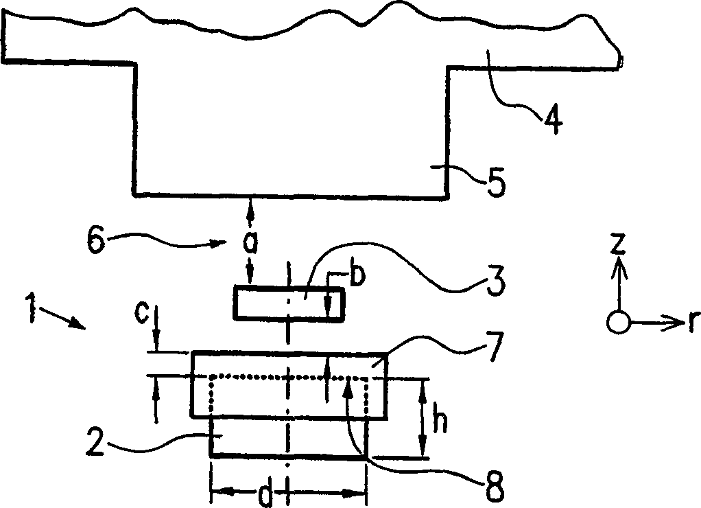
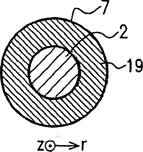
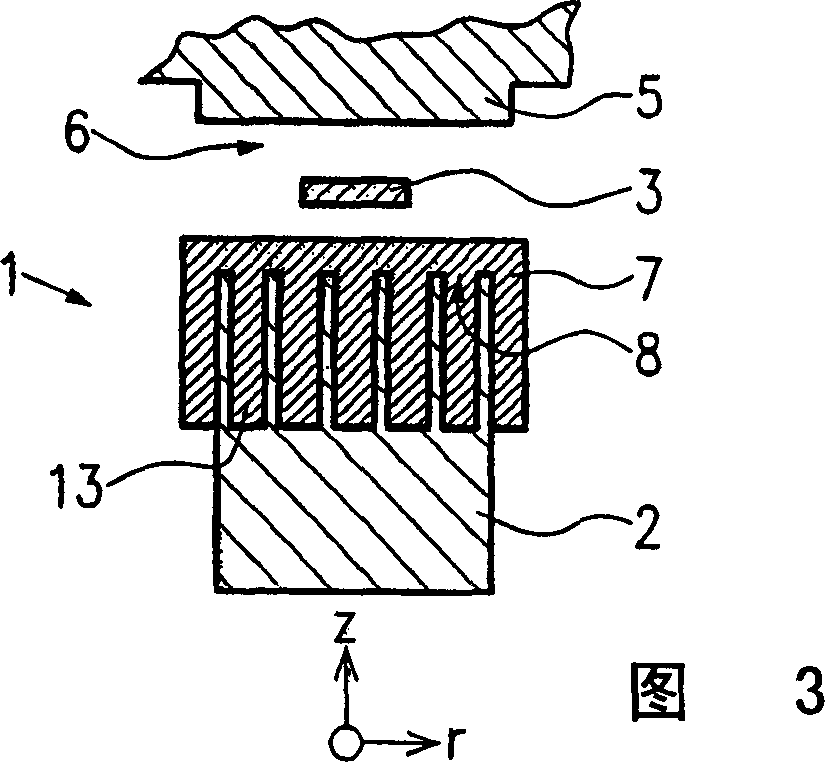
[0035] Such as figure 1 As shown, the measuring device 1 according to the first exemplary embodiment of the invention comprises a permanent magnet 2 which is designed as a bar magnet with a diameter d and a height h. Furthermore, the measuring device 1 comprises a Hall element 3 and a soft magnetic element 7 . The magnetically soft element 7 has a recess 8 for receiving the permanent magnet 2 . Such as figure 1 As shown, the permanent magnet 2 is covered by the soft magnetic element 7 up to half of its height h.

[0036] Instead of the Hall element, other magnetic field sensitive elements can also be used, such as magnetoresistive sensors (anisotropic magnetoresistance effect or giant magnetoresistance effect), field plates and the like. In addition, multiple elements can also be used as differential switches.

[0037] Such as figure 1 As shown, the Hall element 3 is arranged between the soft magnetic element 7 and a tooth 5 of a sensor wheel 4, in an air gap 6 at a dista...


PUM


Abstract

The invention relates to a measuring device (1) for contactlessly detecting a ferromagnetic object (4, 5). The measuring device comprises a Hall element (3) and at least one permanent magnet (2), an air gap (6) being located between said Hall element and said permanent magnet. The permanent magnet (2) also has a soft magnetic component (7) on at least one of its front sides, said component being located between the permanent magnet (2) and the Hall element (3).

Description

[0001] Measuring device for magnetic objects technical field [0002] The invention relates to a measuring device for contactless detection of ferromagnetic objects as claimed in independent claims 1 and 10 . Background technique [0003] Measuring devices of this type generally comprise a magnet structure system and an integrated circuit chip with a Hall element, the chip being arranged at one end of the magnet structure and in the magnetic field formed by the magnet structure. The Hall element generates an electrical signal relative to the strength of the magnetic field perpendicular to the plane of the Hall element. When a ferromagnetic object approaches the Hall element, the strength of the magnetic field perpendicular to the Hall element changes. So the distance from the ferromagnetic object to the Hall element can be reproduced by an electrical signal generated by the Hall element. Hall sensors of this type are used to detect the number of revol...

Claims


Application Information

Patent Timeline
Patent Type & Authority Applications(China)
IPC IPC(8): G01D5/245G01D5/14H01L43/06
CPCG01D5/147G01D5/12
Inventor H·施泰恩吕肯D·黑森伯格M·舒尔茨R·雷蒂M·哈尔斯K·金特纳
Owner ROBERT BOSCH GMBH
Learn More