Measuring device for measuring magnetic properties of surroundings of measuring device
What is Al technical title?
Al technical title is built by PatSnap Al team. It summarizes the technical point description of the patent document.
A technology for measuring devices and magnetic properties, applied in measuring devices, electromagnetic measuring devices, measuring magnetic variables, etc., can solve problems such as degaussing of hard magnetic materials
Active Publication Date: 2014-05-21
精量电子(德国)公司
View PDF16 Cites 6 Cited by
Summary
Abstract
Description
Claims
Application Information
AI Technical Summary
This helps you quickly interpret patents by identifying the three key elements:
Problems solved by technology
Method used
Benefits of technology
Problems solved by technology
This can cause degaussing of hard magnetic materials
Method used
Image
Click on the blue label to locate the original text in one second.
Reading with bidirectional positioning of images and text.
Examples
Embodiment Construction
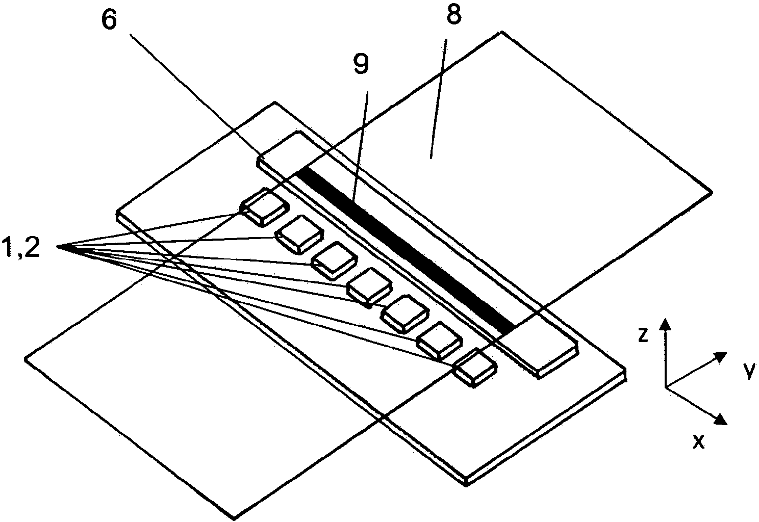
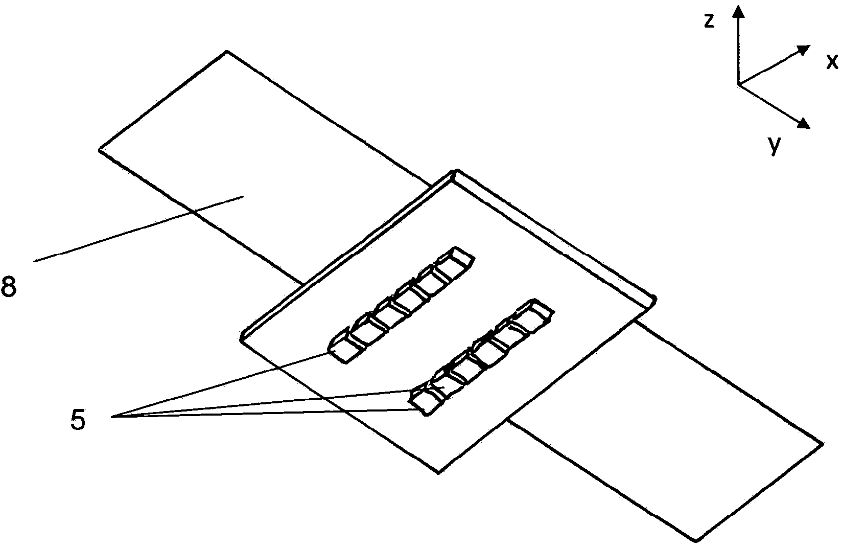
[0092] Figure 1 to Figure 12 Shown is an embodiment of a measuring device for measuring magnetic properties around a measuring device, i.e. for checking documents or paper, in particular banknotes, checks or other paper, for the presence or absence of magnetic features, in particular whether said documents or paper have special , Measuring device for pre-specified magnetic characteristics.
[0093] Figure 1 to Figure 12 The measuring devices shown each have a sensor column 2 consisting of sensor elements 1 . like Figure 13 As shown, sensor element 1 has magnetoresistive bridge resistors 4 arranged on substrate 3 and connected to form a Wheatstone bridge. If external resistors are used, one bridge resistor 4 can be used per sensing element 1 . The sensor elements 1 can be combined into groups, ie form so-called sensors. The bridge resistor 4 has an AMR effect. By means of this bridge circuit, the sensor element 1 is able to measure the magnetic properties of its surrou...
PUM
Abstract
The invention relates to a measuring device for measuring the magnetic properties of the surroundings of the measuring device by means of a sensor line having at least one magnetoresistive sensor element extending in a line direction, which can measure the magnetic properties in the surroundings thereof, wherein the sensor element has a width and a length as well as a height, wherein the height is smaller than the width, and the height is smaller than the length, and the line direction points in the direction of the width or in the direction of the length of the sensor element, and having a support field device which generates a magnetic support field in the area over which the sensor line extends, having a premagnetization device which comprises a premagnetization magnet or several premagnetization magnets, wherein at least one premagnetization magnet is arranged in a direction which is perpendicular to the line direction, spaced from the sensor line, and extends in a direction parallel to the line direction, characterized in that magnetoresistive sensor element can measure the magnetic properties of the surroundings thereof substantially in only one direction, referred to as the measurement direction, of an orthogonal coordinate system, or substantially in only one plane, referred to as the sensor measurement plane, which is defined by two perpendicular measurement directions of an orthogonal coordinate system, in that, in the case of a premagnetization device which consists of only one premagnetization magnet, the properties of the premagnetization magnet, which influence the magnetic field generated by said magnet and the arrangement of said magnet relative to the sensor cell as well as the support field generated by the support field device are selected in such a manner that an overlap magnetic field forms due to the overlap of the magnetic field generated by the premagnetization device and of the support field, wherein the strength of the field component of said overlap magnetic field, which points in the line direction is, at least at one site on the sensor line, greater than the strength of the field component which is perpendicular to the line direction and does not point in the direction of the height of the sensor element, or in the case of a premagnetization device consisting of several premagnetization magnets, the properties of the premagnetization magnet, which influence the magnetic field generated by said magnets, and the arrangement of the premagnetization magnets relative to the sensor cell as well as the support field generated by the support field device are selected in such a manner that an overlap magnetic field forms due to the overlap of the magnetic field generated by the premagnetization device and of the support field, wherein the strength of the field component of said overlap magnetic field, which points in the line direction is, at least at one site on the sensor line, greater than the strength of the field component which is perpendicular to the line direction and does not point in the direction of the height of the sensor element.
Description
technical field [0001] The invention relates to a measuring device for measuring magnetic properties in the vicinity of a measuring device. [0002] The invention can be used for checking documents or papers, especially banknotes, checks or other papers, for the presence or absence of magnetic characteristics, especially for checking whether said documents or papers have specific, pre-assigned magnetic characteristics. Background technique [0003] Magnetic materials used on securities are generally relatively small in size. Therefore, the strength of the stray magnetic field of the security thread is only a few amps / meter at a few millimeters away from the security thread. Verifying such weak stray fields requires the use of very sensitive sensors. Therefore, the measuring device used in actual operation requires the distance between the sensor and the value document to be no more than 1 mm. Furthermore, only a few techniques are suitable for identifying such weak locali...
Claims
Application Information
Patent Timeline
Application Date:The date an application was filed.
Publication Date:The date a patent or application was officially published.
First Publication Date:The earliest publication date of a patent with the same application number.
Issue Date:Publication date of the patent grant document.
PCT Entry Date:The Entry date of PCT National Phase.
Estimated Expiry Date:The statutory expiry date of a patent right according to the Patent Law, and it is the longest term of protection that the patent right can achieve without the termination of the patent right due to other reasons(Term extension factor has been taken into account ).
Invalid Date:Actual expiry date is based on effective date or publication date of legal transaction data of invalid patent.