
Chemical applying method and its applying device

A coating device and liquid medicine technology, which is applied to the surface coating liquid device, transmission device, gear transmission device, etc., can solve the problems of non-concentrated high-pressure air flow, gap difference, and difficulty in uniform dispersion of liquid medicine, etc.

Inactive Publication Date: 2003-02-12
NEC LCD TECH CORP
View PDF1 Cites 11 Cited by
  • Summary
  • Abstract
  • Description
  • Claims
  • Application Information

AI Technical Summary

Problems solved by technology

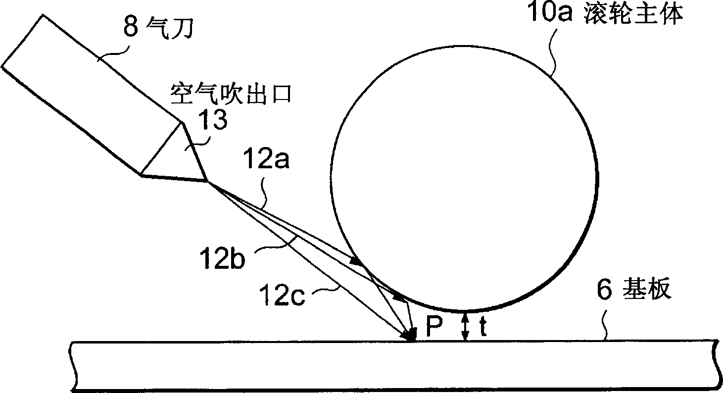
[0006] However, in the above-mentioned existing coating method, such as Figure 8 As shown in the explanatory diagram of , in order to make the air flow blown out from the air knife 8 uniform, it is necessary to strictly adjust the gap of the air blowing port 13
Adjustment is made with set screw 16 (shown in Figure 9 ), but if adjusted poorly, there will be a difference in clearance no matter where
Therefore, the blowing direction of the high-pressure air 12a, 12b, 12c blown out from the air blowing port 13 is scattered, and the flow of the high-pressure air is not concentrated. Even if the angle of the air knife 8 is adjusted, the dispersion cannot be eliminated.
[0007] Especially in the case of a large substrate such as a glass substrate for liquid crystal, it is difficult to uniformly disperse the chemical solution on the substrate, and it is difficult to uniformly apply the chemical solution dispersed in the direction perpendicular to the direction of travel of the substrate. As a result, as Figure 9 As shown in the top view of , only the air knife 8 cannot sufficiently prevent the flow and spread of the chemical solution 11 on the substrate 6, and uneven coating 15 occurs in the coated chemical solution 11, and after the coating of the substrate 6 is completed, remaining The substrate 6 affected by the coating unevenness 15 is transported to the next process
In the portion affected by the uneven coating 15, the coating thickness of the chemical solution is also uneven, which is likely to have an adverse effect on the next process.
[0008] Therefore, in the conventional chemical solution coating method and apparatus, only the air knife suppresses the chemical solution insufficiently to cause coating unevenness, and the substrate is conveyed while remaining affected by the coating unevenness. to the next process
For example, if the chemical solution application process is a cleaning solution application process, the influence of uneven application cannot be removed in the cleaning solution removal process of the next process, and it remains, which becomes the cause of poor cleaning.

Method used


Image

  • Chemical applying method and its applying device
  • Chemical applying method and its applying device
  • Chemical applying method and its applying device

Examples


Embodiment Construction

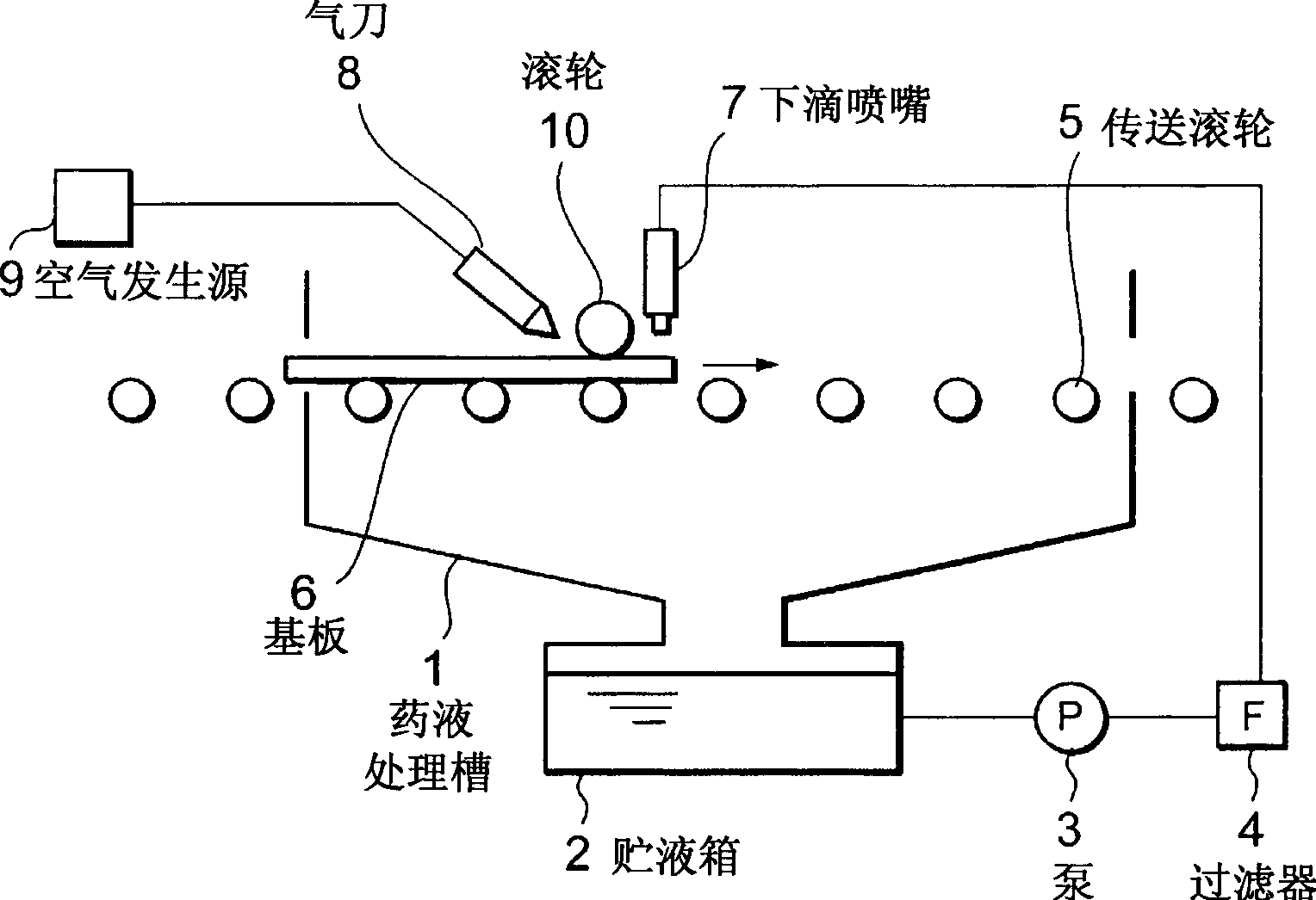
[0025] Embodiments of the present invention will be described below with reference to the drawings. figure 1 It is a schematic configuration diagram of the chemical solution application device used in the present invention. In addition, the same parts as those of the conventional device are described with the same reference numerals.

[0026] Such as figure 1 As shown, the liquid medicine coating device of the present invention includes: a liquid medicine treatment tank 1, which is used to apply the liquid medicine on a large substrate 6 such as a glass substrate for liquid crystal; (exist figure 1 The middle is the left end) Carry the substrate 6 into the chemical solution processing tank 1 at a certain speed, and from the other end of the chemical solution processing tank 1 ( figure 1 The middle is the right end) The substrate is carried out at a certain speed to the delivery part outside the liquid medicine treatment tank 1; the liquid storage tank 2 of the liquid me...


PUM


Abstract

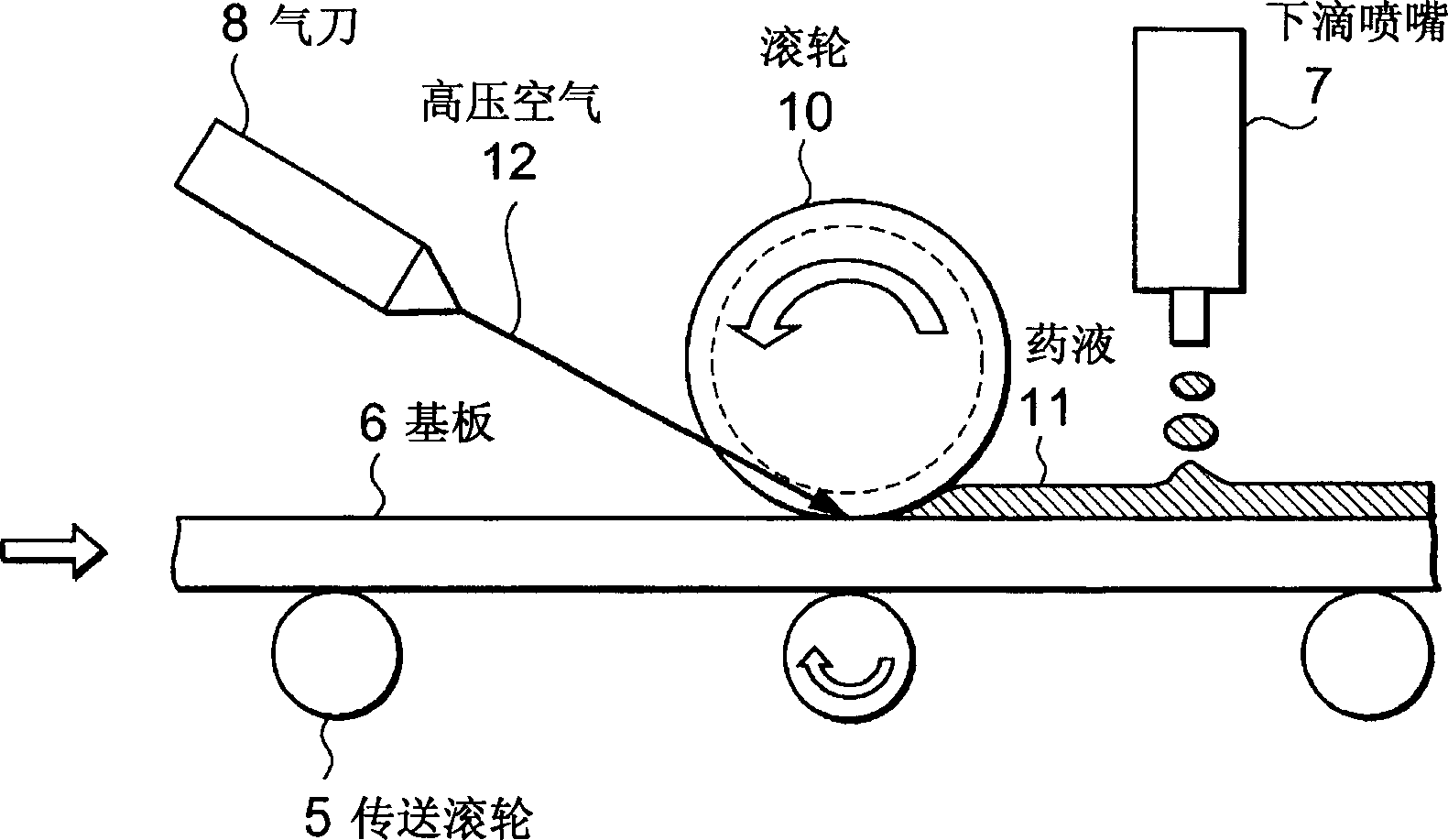
The invention provides a liquid medicine coating method and coating device. In order to eliminate the coating application unevenness which arises in a applied liquid medicine by disposing liquid stopping means capable of sufficiently stopping the liquid medicine spreading by flowing on a substrate when the liquid chemical is applied to the substrate of a large size, like a glass substrate for liquid crystals. Characterized in that, the flange part 1 includes conveyance rollers 5 for conveying the substrate 6, a dripping nozzle 7 for dripping the liquid medicine onto the substrate 6 under conveyance, a roller 10 (first liquid medicine stopping means) arranged closer to the upstream side position relative to the progressing direction of the substrate than position of the dripping nozzle 7; and an air knife 8 arranged closer to the upstream side position relative to the progressing direction than the roller 10 (total liquid medicine stopping means).

Description

technical field [0001] The present invention relates to a liquid medicine coating method and a coating device thereof. For example, when coating a liquid medicine on a glass substrate for liquid crystals, the method and the device can efficiently suppress the liquid medicine to uniformly adjust the spread of the medicine liquid, so that Uneven coating does not occur in the treated liquid. Background technique [0002] Next, a conventional chemical solution application device will be described with reference to the drawings. Figure 6 It is a schematic configuration diagram of a conventional chemical solution application device. Such as Figure 6 As shown, the existing liquid medicine coating device includes: a liquid medicine treatment tank 1, which coats the liquid medicine on a large-sized substrate 6 such as a glass substrate for liquid crystal; The substrate 6; the liquid medicine storage tank 2, which is arranged at the bottom of the liquid medicine treatment tank 1; t...

Claims


Application Information

Patent Timeline
IPC IPC(8): G03F7/16B05C3/18B05C5/00B05C11/02B05C11/06B05C11/10B05D1/26B05D1/30B05D1/36B05D3/00H01L21/027
CPCF16H3/08F16H3/363
Inventor 前园武志
Owner NEC LCD TECH CORP
Learn More