Beat frequency detection method for travelling-wave annular resonance cavity of non-mechanical gyro

A technology of a ring resonant cavity and a detection method, which is applied in the field of gyroscopes, can solve problems such as sensitivity to parasitic effects, and achieve the effects of improved measurement accuracy and easy miniaturization

Inactive Publication Date: 2002-12-04
优创科技(深圳)有限公司
View PDF0 Cites 14 Cited by
  • Summary
  • Abstract
  • Description
  • Claims
  • Application Information

AI Technical Summary

Problems solved by technology

[0004] On the basis of careful analysis of the Sagnac effect principle and detection mechanism, the present invention proposes a detection method based on a traveling wave ring resonator beat frequency gyroscope, which overcomes existing non-mechanical gyroscopes such as fiber optic gyroscopes, especially interferometric I-FOG and resonant gyroscope R -FOG is sensitive to many parasitic effects

Method used


Image

  • Beat frequency detection method for travelling-wave annular resonance cavity of non-mechanical gyro
  • Beat frequency detection method for travelling-wave annular resonance cavity of non-mechanical gyro
  • Beat frequency detection method for travelling-wave annular resonance cavity of non-mechanical gyro

Examples


Embodiment

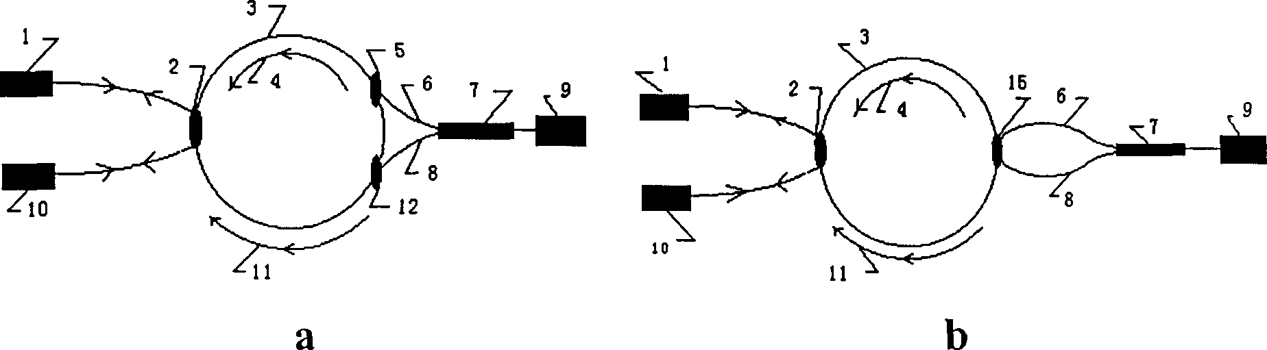
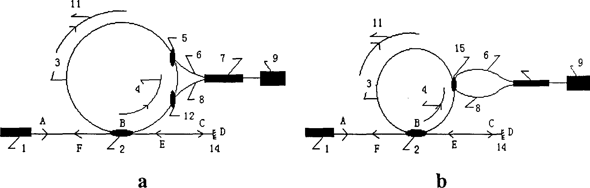
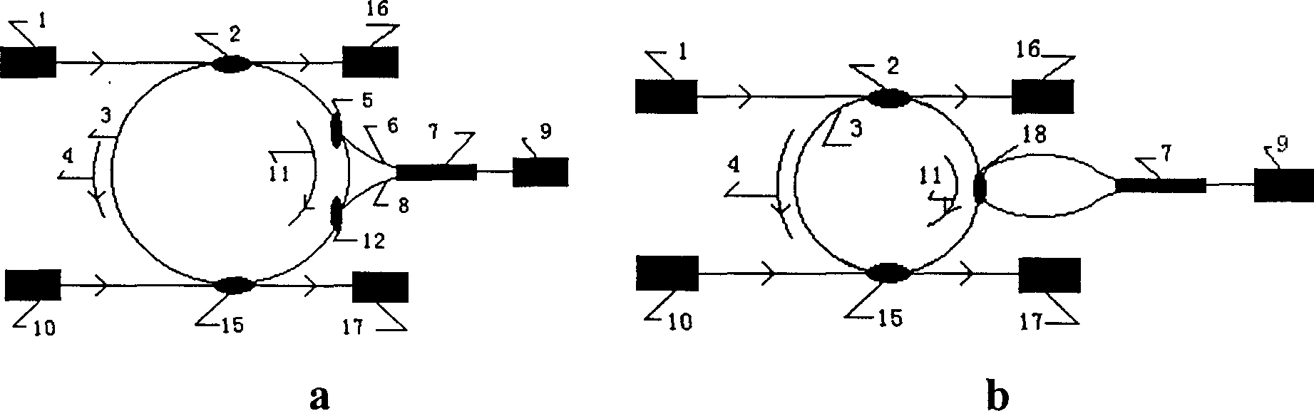
[0038] Such as Figure 5 shown, based on figure 1 (a) An embodiment of the schematic structure shown in optical fiber. In the figure, LR is a broadband light source such as a super fluorescent light source; C 1 and C 4 for 1 x 2 fiber optic waveguide couplers, C 2 and C 3 is a 2×2 fiber optic waveguide coupler; R is a fiber resonator whose parameters match the bandwidth of the light source; P is an optional polarization beam splitter whose presence or absence does not affect the position of the beat frequency, but will affect its peak value; BD is Photoelectric conversion, low-pass filtering, beat frequency detection (instantaneous frequency measurement), S is calculation and display of angular velocity.

[0039] will be like Figure 5 The device shown in is placed in an inertial system, the light emitted by the light source LR passes through the coupler C 1 After split into two beams, and through 2×2 coupler C 2 Both couple part of the light waves into the optical fib...


PUM


Abstract

The invention discloses the method for measuring the beat frequency of the non-mechanical optical gyro by using the ring travelling wave resonant cavity. Further, the angular speed of inertial systemis measured. The ring travelling wave resonant cavity is positioned on the inertial system, which is rotated at certain angular speed. The otpical signal feeds-in-the ring travelling wave resonant cavity by usnig 2X2 wave-guide coupler, thus light wave field propagates to both of the clockwise direction and anti-clockwise direction. The beat frequency signal can be obtained by superposing the tworesonant optical signals with different frequencies, which can be obtained by using the wave guide coupler to couple directly from the travelling wave resonant cavity. The low-pass filter takes out the beat frequency signal, whose frequency value and variety is corresponding to the angular speed and variety of inertial system.

Description

Technical field: [0001] The invention belongs to the technical field of gyroscopes, in particular to a method for detecting the angular velocity of an inertial system based on the beat frequency of a traveling wave ring resonant cavity (optical fiber) gyroscope. Background technique: [0002] The most important new gyroscope technology at the beginning of the 21st century is non-mechanical optical gyroscope technology. Among the many new gyroscopes, non-mechanical optical gyroscopes, including laser gyroscopes and fiber optic gyroscopes, will form a major role in the current and future inertial system measurements. The situation of competing with traditional mechanical gyroscopes for the market has been eliminated. This kind of gyroscope works based on the principle of the constant speed of light, which is different from the original inertial instrument in the mechanical sense. It has neither high-speed rotating parts nor liquid like a liquid floating gyroscope, and is a sol...

Claims


Application Information

Patent Timeline
Patent Type & Authority Applications(China)
IPC IPC(8): G01C19/58
Inventor 李正斌吴德明徐安士
Owner 优创科技(深圳)有限公司
Why Eureka
Try Eureka