Power supply system for arc welding
An arc welding power supply and transformer technology, applied in welding equipment, arc welding equipment, circuits, etc., can solve the problems of narrow power supply voltage adaptability, low power factor, power supply pollution, etc., to achieve no power supply pollution, high power factor, The effect of a large voltage range
- Summary
- Abstract
- Description
- Claims
- Application Information
AI Technical Summary
Problems solved by technology
Method used
Image

Examples
Embodiment 1
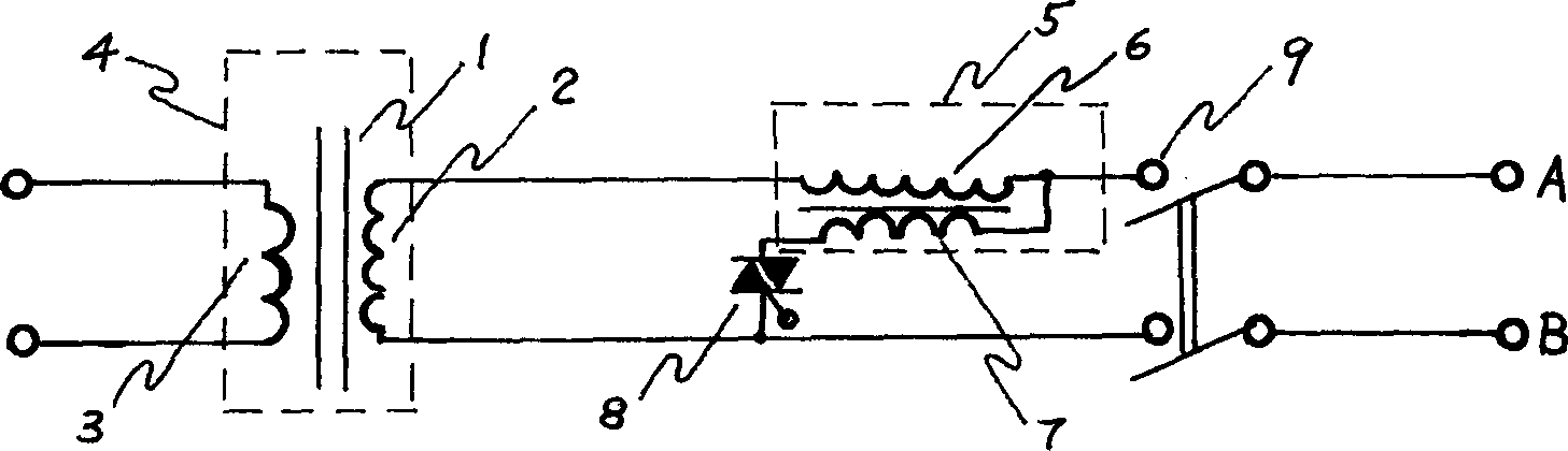
[0017] Example 1. As figure 1 As shown, this is an arc welding power supply system for welding, which is a single-phase AC power supply. It consists of an iron core and a transformer consisting of a primary winding and a secondary winding. An autotransformer compensation transformer is also connected to the primary winding of the transformer. The secondary winding of the autotransformer is connected in series with one end of the primary winding of the transformer, and its primary winding is connected in series with its secondary winding, then connected in series with the bidirectional thyristor, and finally connected to the other end of the primary winding of the transformer. The series end taps of the primary winding and the secondary winding of the autotransformer are connected to the power supply. The operating design value of the magnetic induction intensity of the iron core of the transformer is much smaller than its saturation magnetic induction intensity.
Embodiment 2
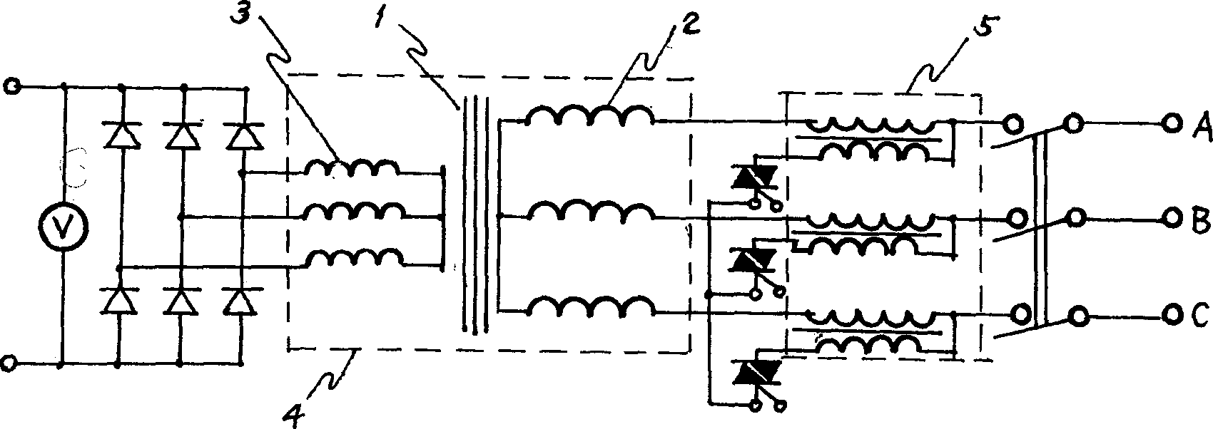
[0018] Example 2. If figure 2 shown. An arc welding power supply system for welding, which is the case under the characteristics of a three-phase DC power supply. Both the transformer and the self-coupling compensating transformer are three-phase, and their iron cores are Japanese-shaped. Both the primary winding and the secondary winding of the transformer are wound on the middle leg of the zigzag iron core. The operating design value of the magnetic induction intensity of the iron core of the transformer is much smaller than its saturation magnetic induction intensity.
Embodiment 3
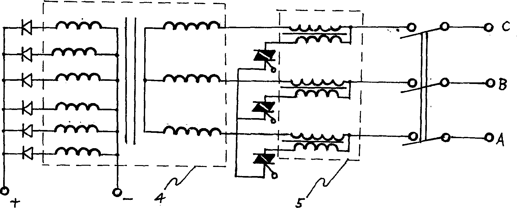
[0019] Example 3. As image 3 shown. An arc welding power supply system for welding is the case of the flat characteristic of the three-phase DC power supply. Both the transformer and the self-coupling compensating transformer are three-phase, and their iron cores are Japanese-shaped. Both the primary winding and the secondary winding of the transformer are wound on the middle leg of the zigzag iron core. The operating design value of the magnetic induction intensity of the iron core of the transformer is much smaller than its saturation magnetic induction intensity.
[0020] Embodiments 1 to 3 have high power factor, stable arc, no power source pollution, low manufacturing cost and energy saving. It can be widely used in AC and DC welding of various metal materials.
PUM
 Abstract
Description
Claims
Application Information
 - R&D
- Intellectual Property
- Life Sciences
- Materials
- Tech Scout
- Unparalleled Data Quality
- Higher Quality Content
- 60% Fewer Hallucinations
Browse by: Latest US Patents, China's latest patents, Technical Efficacy Thesaurus, Application Domain, Technology Topic, Popular Technical Reports.
© 2025 PatSnap. All rights reserved.Legal|Privacy policy|Modern Slavery Act Transparency Statement|Sitemap|About US| Contact US: help@patsnap.com