Electric resistance welder

A resistance welding and electric power technology, applied in the field of resistance welding devices, can solve the problems of shortening the loop distance, high device cost, and difficulty in miniaturizing the power supply part, and achieve the effect of preventing damage

Inactive Publication Date: 2002-07-03
MIYACHI TECHNOS CORP
View PDF0 Cites 0 Cited by
  • Summary
  • Abstract
  • Description
  • Claims
  • Application Information

AI Technical Summary

Problems solved by technology

And, because the connecting conductor of loop L adopts the structure of copper bar 100,102,104 in the existing device, it is difficult to shorten the loop distance
Therefore, a protection circuit (not shown) such as a snubber circuit is provided in the transistor 14 as a countermeasure against the surge voltage, and the device cost is high.
In addition, since the overall length of the loop L is large, it is also difficult to reduce the size of the power supply unit.

Method used


Image

  • Electric resistance welder
  • Electric resistance welder
  • Electric resistance welder

Examples


Embodiment Construction

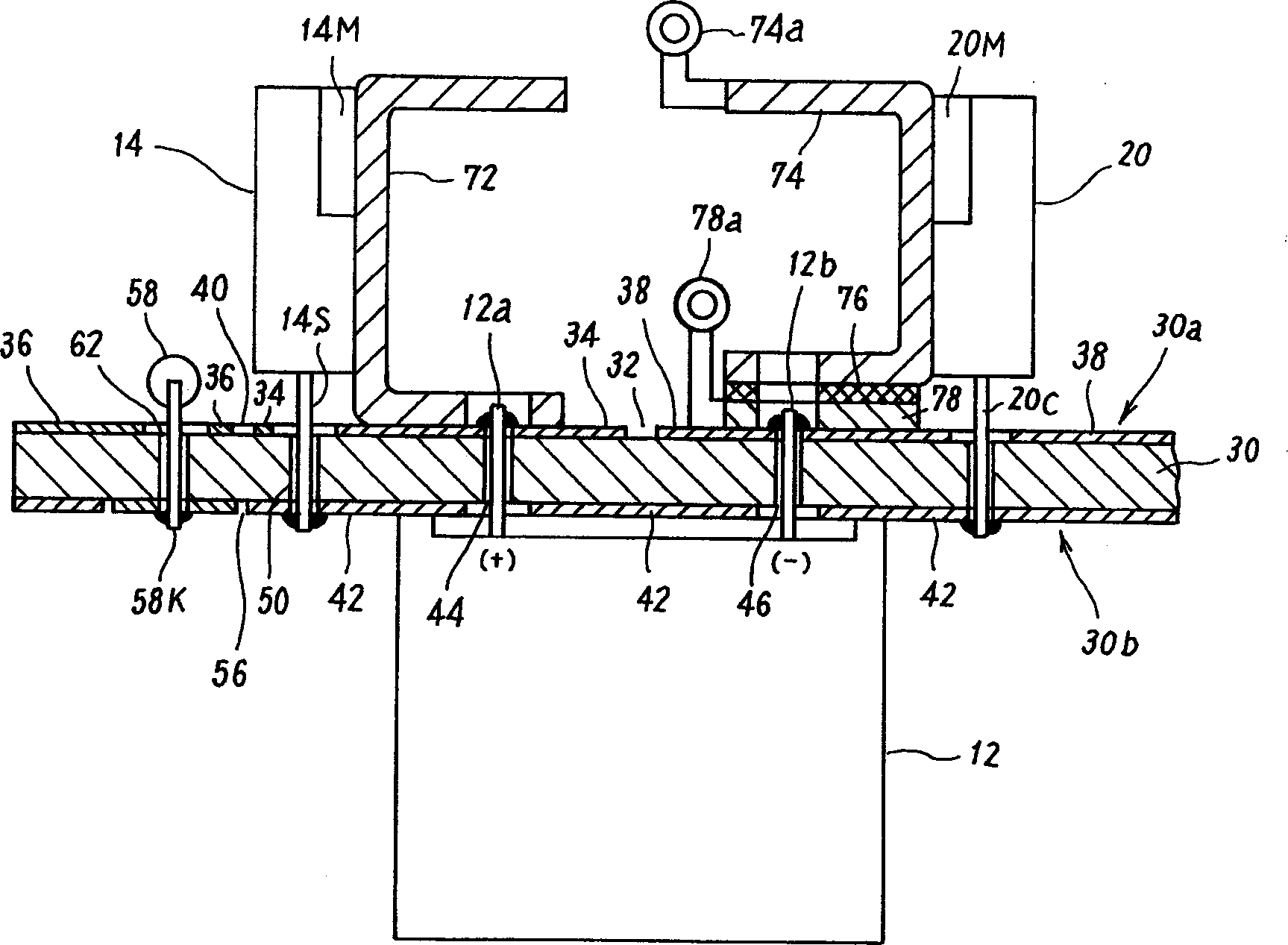
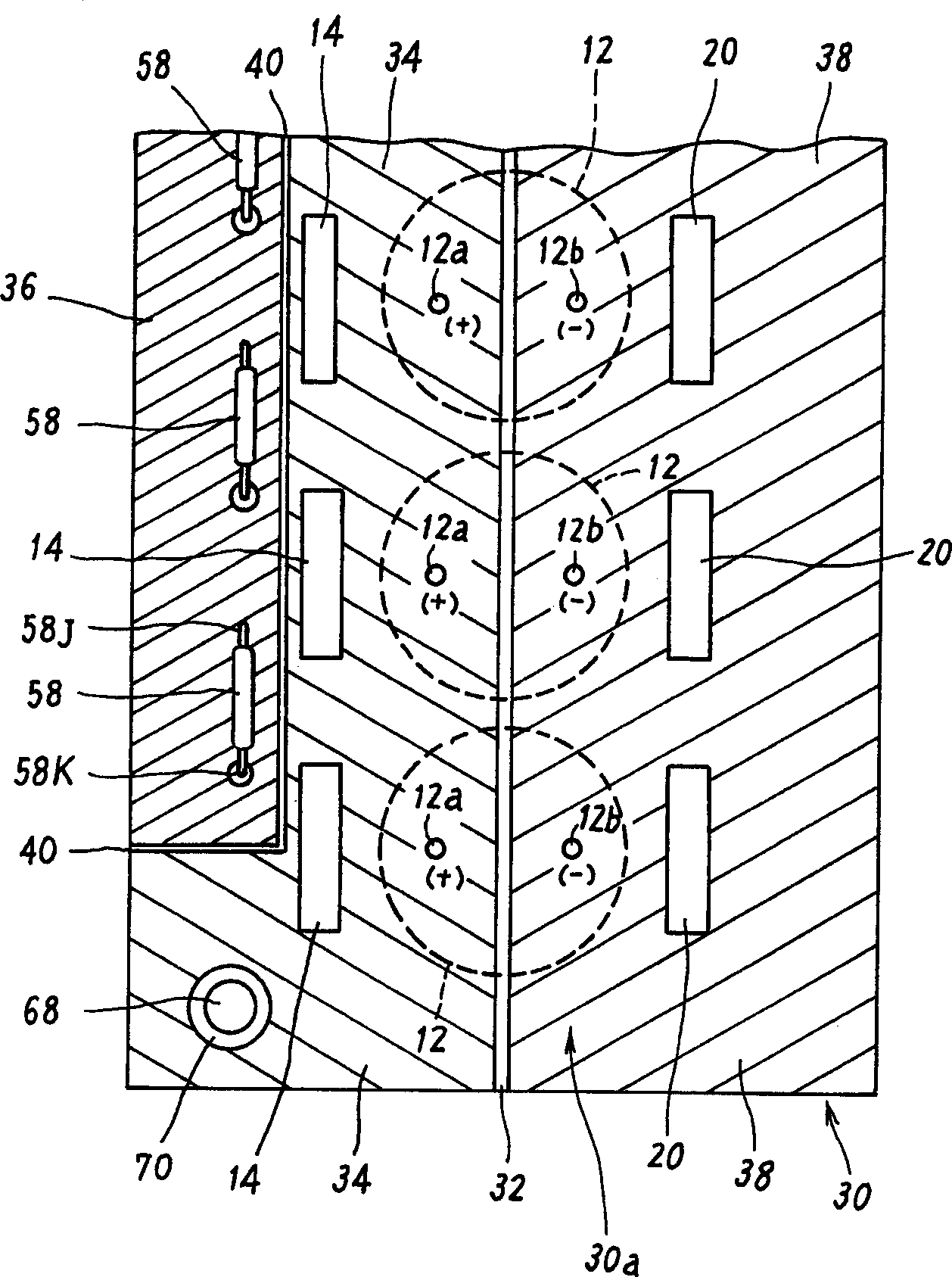
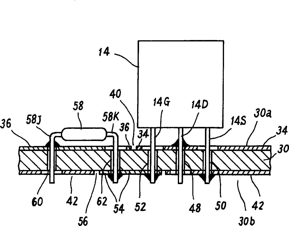
[0022] Refer below Figure 1 to Figure 5 , illustrating an ideal embodiment of the present invention.

[0023] Figure 1 to Figure 5 It shows the assembly structure of the main part of the resistance welding apparatus of one embodiment of the present invention. The resistance welding device of this embodiment also has Image 6 The circuit structure, such as figure 1 Combinations shown include Image 6 The capacitor 12, the switching transistor 14 and the freewheeling diode 20 of the circuit.

[0024] In this combination, for example, a substrate 30 made of an insulating material such as glass epoxy resin is used as a main body, and one side of the substrate 30 ( figure 1 The lower side of the) install the capacitor 12, on the opposite side ( figure 1 The upper side) of the switch transistor 14 and the freewheeling diode 20 are installed.

[0025] Conductive film conductors made of, for example, copper foil are fixedly formed on both surfaces of the substrate 30 by elec...


PUM


Abstract

To realize safety of a switching element by reducing surge voltage which is generated immediate after the switching element is off. In a power supply assembly, capacitor 12, switching/transistor 14 and fly-wheel diode are formed on base plate 30, an each part is electrically connected through thin film conductors 34, 38 and 42 which are formed on both faces of a base plate 30. In detail, a positive electrode side terminal 12a of a capacitor 12 and a current in a side terminal (not illustrated) of a switching/transistor 14 are electrically connected on a base board upper face 30a side through the thin film conductor 34 for a positive electrode side conductive path. A current outside terminal 14S of the switching/transistor 14 and a cathode terminal 20C of a flywheel diode 20 are electrically connected on a base board lower face 30b side through the thin film conductor 42 for a positive electrode side conductive path. A negative electrode side terminal 12b of the capacitor 12 and an anode terminal (not illustrated) of the flywheel diode 20 are electrically connected on the base board upper face 30a side through the thin film conductor 38 for a negative electrode side conductive path.

Description

technical field [0001] The present invention relates to a resistance welding device, and more particularly to a resistance welding device in which electric power as welding energy is stored in a capacitor and then supplied to a welded part through a switching element. Background technique [0002] Image 6 Shows the basic circuit configuration of the main parts of this resistance welding device. The charging circuit 10 includes, for example, a single-phase full-wave rectification circuit composed of a plurality of bridge-connected diodes. The single-phase AC power supply voltage Ea of commercial frequency is input from the AC power line through an insulating transformer (not shown), and the input AC power supply voltage Ea is full-wave Rectification, output DC voltage. The capacitor 12 is charged at a predetermined voltage value Ec by the output voltage of the charging circuit 10 . [0003] The positive side terminal of the capacitor 12 is electri...

Claims


Application Information

Patent Timeline
Patent Type & Authority Applications(China)
IPC IPC(8): B23K11/26B23K11/24
CPCB23K11/24
Inventor 渡辺干男
Owner MIYACHI TECHNOS CORP
Why Eureka
Try Eureka