
On cell circumferential battery indicator

A battery and peripheral technology, applied in the field of battery detectors, can solve the problems of reducing battery life, difficulty in distinguishing detectors, and difficult for people to press switches.

Inactive Publication Date: 2002-05-01
THE GILLETTE CO
View PDF0 Cites 0 Cited by
  • Summary
  • Abstract
  • Description
  • Claims
  • Application Information

AI Technical Summary

Problems solved by technology

At the same time, the switch is sometimes difficult for a person to press, and it becomes difficult to distinguish whether the detector is working or not working, or the battery is good or bad
This can be confusing for consumers
Pressing the switch creates a direct, relatively high conductance contact between the anode and cathode of the battery, which can draw considerable power and reduce the life of the battery

Method used


Image

  • On cell circumferential battery indicator
  • On cell circumferential battery indicator
  • On cell circumferential battery indicator

Examples


Embodiment Construction

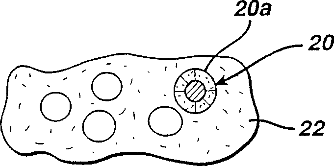
[0026] see figure 1 , figure 1 A metal-insulator-metal diode 10 is shown. The metal-insulator-metal diode 10 includes a first electrode 12, for example, a copper foil substrate or another conductive material such as carbon or gold, or other conductive material such as chromium, tungsten, molybdenum, or other such as dispersed in Metal particles in polymer binders such as conductive inks. The metal-insulator-metal diode 10 also includes a composite metal-insulator layer 14 comprising metal particles 20 suspended in a dielectric bonding layer 22 . Such as Figure 1A As shown, the metal particle 20 has an intrinsic oxide layer 20a covering the surface of the particle 20 . A preferred metal is tantalum, which readily forms an inherently stable and generally uniform native oxide layer 20a. Other metals like niobium can also be used. These other metals should form self-limited stable oxides and have suitable dielectric constants for the application. One reason tantalum is pre...


PUM


Abstract

A battery includes a battery tester including a display that is disposed around a substantial portion of the circumference of the battery. Also describe is a battery operated electronic device including a case that houses electronic components that comprise the electronic device, said case including a door that opens up to a battery compartment, with the door having at least a transparent window portion in the door.

Description

field of invention [0001] The present invention relates to battery testers which are incorporated into battery labels or packaging. technical background [0002] Various types of battery testers are known which are placed on the battery, so-called "thermochromic" type testers. In detectors of the thermochromic type, a thermochromic display is placed as a narrow, elongated area of ​​the label. Typically the display device is a single narrow elongated area. The consumer presses the manual switch, and the thermochromic battery detector can detect. Once the switch is pressed, the consumer connects the anode and cathode of the battery and can read the relative power remaining in the battery. The connection is through a silver conductor of variable width so that the resistance of the conductor varies along its length. When current flows through the silver conductor, the current generates heat that changes the color of the thermochromic ink in the thermochromic display device o...

Claims


Application Information

Patent Timeline
IPC IPC(8): G01R31/36H01M6/50H01M10/48H01M50/202H01M50/233H01M50/271
CPCY02E60/12H01M2/1055H01M2/1066H01M2/1094H01M6/505G01R31/3686H01M2/1022H01M10/488H01M10/48Y02E60/10H01M50/213H01M50/24H01M50/233H01M50/202H01M50/271
Inventor 马克·卡克普劳维兹安·T·莱恩克埃里克·S乔顿戴维·N·克莱恩
Owner THE GILLETTE CO
Learn More