Mandrel of printing equipment, printing cylinder and printing equipment

A technology for printing cylinders and printing equipment, applied to the general parts of printing machinery, printing, printing machines, etc., can solve the problems of complex compression gasket structure, limited clamping force, etc., and achieve improved total indication deviation and high throughput speed , good printing quality effect

Active Publication Date: 2019-03-12
MPS HLDG
View PDF21 Cites 0 Cited by
  • Summary
  • Abstract
  • Description
  • Claims
  • Application Information

AI Technical Summary

Problems solved by technology

However, the clamping force achievable with axially compressible washers is limited, and the configuration for compressing washers is complex

Method used


Image

  • Mandrel of printing equipment, printing cylinder and printing equipment
  • Mandrel of printing equipment, printing cylinder and printing equipment
  • Mandrel of printing equipment, printing cylinder and printing equipment

Examples


Embodiment Construction

[0045] In the present application, similar or corresponding features are indicated by similar or corresponding reference numerals. The description of various embodiments is not limited to the examples shown in the drawings, and reference numerals used in the detailed description are not intended to limit the description of the embodiments. Reference numerals are included to clarify the embodiments by referring to the examples shown in the figures.

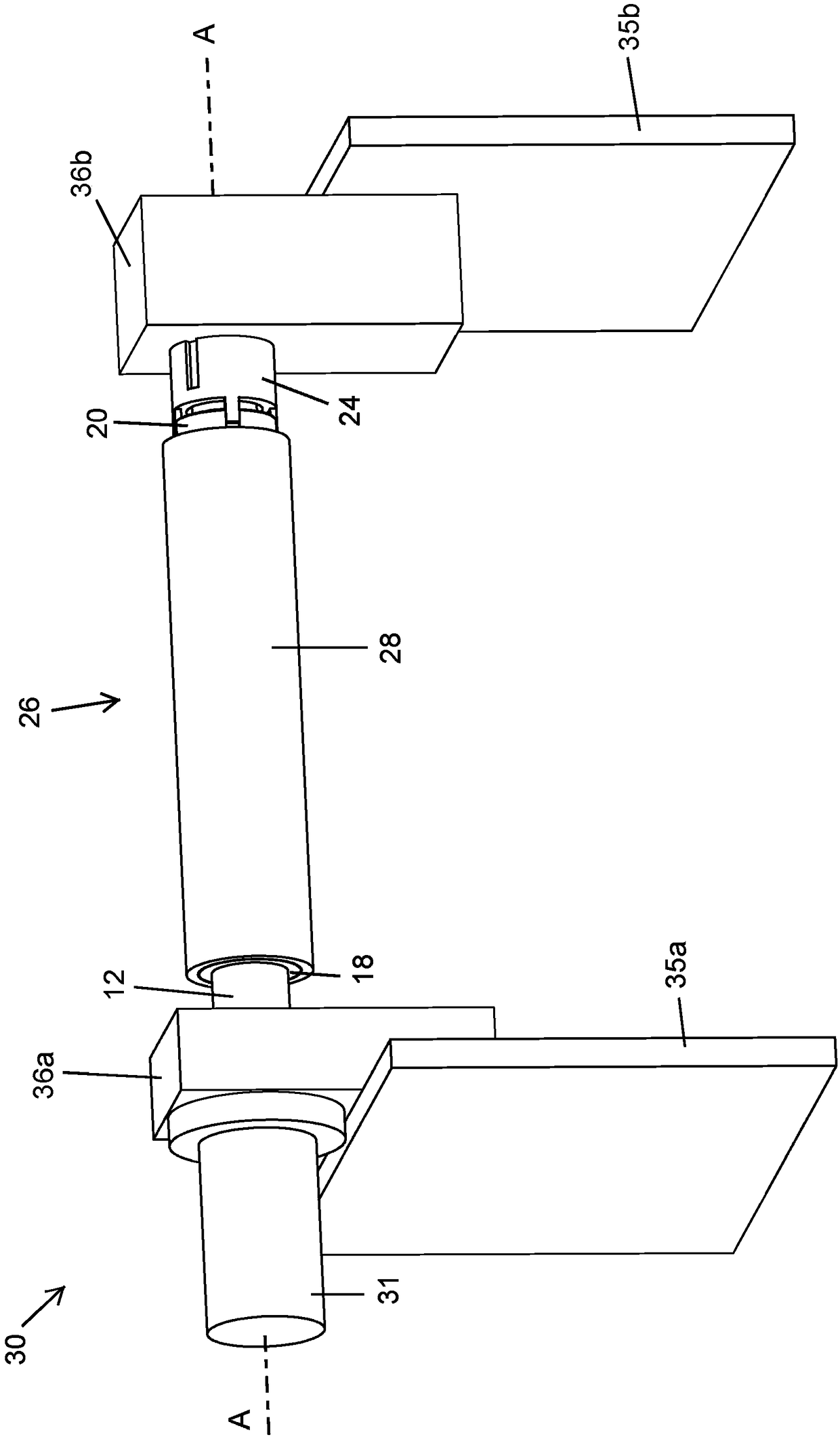
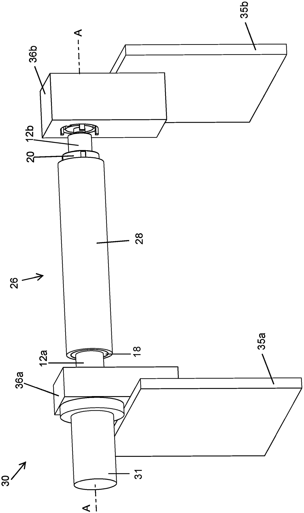
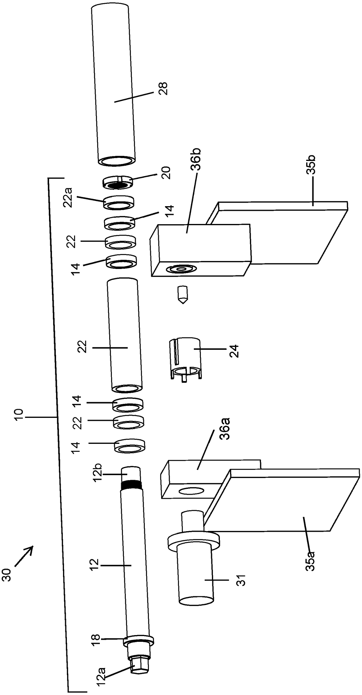
[0046] Broadly, the mandrel 10 includes a generally cylindrical mandrel shaft 12 extending along a mandrel axis A and a plurality of expandable rings 14 slidably and coaxially mounted on the mandrel shaft 12 . Each expandable ring 14 expands radially outward when the expandable rings 14 are axially compressed. The mandrel 10 also includes a locking assembly comprising a stop ring 18 having an axially fixed position on the mandrel shaft 12 adjacent the first end 12a of the mandrel shaft 12, and a locking ring 20 for locking Ring 2...


PUM


Abstract

A mandrel for printing equipment. The mandrel includes a generally cylindrical mandrel shaft and a plastic expansion ring slidably and coaxially mounted on the mandrel shaft. The mandrel also includes a locking assembly comprising a fixed stop ring and a single locking ring axially movably mounted on the mandrel shaft. An expansion ring is located between the stop ring and the locking ring. In the unlocked position of the locking ring, the expansion ring 14 is in a released state in which the axial compression and radial expansion of the expansion ring is less than in the locked position of the locking ring. The print cylinder sleeve may be fixedly connected to the mandrel by placing the expansion ring in a radially expanded state. This is possible when the expansion ring is loose when the printing cylinder sleeve has to be replaced.

Description

technical field [0001] The present invention relates to a mandrel, and a sleeve-type printing cylinder for a printing apparatus having such a mandrel. The invention also relates to a printing machine comprising such a sleeve-type printing cylinder and to a method of printing. Background technique [0002] The use of printing cylinders comprising mandrels and printing sleeves is known in the art, eg for flexographic or (lithographic) offset printing. Typically, the mandrel is an air mandrel comprising a rigid cylinder, such as a steel shaft, on which the printing sleeve is removably mounted. The cylindrical surface of the air mandrel contains outflow openings through which air can be supplied when the sleeve has to be mounted on or removed from the mandrel. Various print sleeves with different radii can be fitted to provide the print cylinder diameter required for the print job. The image to be printed is provided directly on the printing sleeve, or it may be provided on a...

Claims


Application Information

Patent Timeline
Patent Type & Authority Patents(China)
IPC IPC(8): B41F13/008B41F27/10B41F30/00B41F7/04B41F5/24
CPCB41F5/24B41F7/04B41F13/008B41F27/105B41F30/00B41P2227/20B41F30/02B41F30/04B41P2227/21
Inventor H·T·G·温特杰斯
Owner MPS HLDG
Why Eureka
Try Eureka