Switch

A switch and switch box technology, applied in the field of switches, can solve problems such as insufficient connections, inability to confirm the condition of insulating parts, troubles, etc.

Inactive Publication Date: 2002-03-27
ENERGY SUPPORT CORP
View PDF1 Cites 8 Cited by
  • Summary
  • Abstract
  • Description
  • Claims
  • Application Information

AI Technical Summary

Problems solved by technology

However, the connection between the above insulating parts is not sufficient
The resulting problem is that when the circuit is disconnected, due to the violent action of the movable electrode and the opening and closing mechanism that rotates the movable electrode, the installation positions of the various insulating components are relatively shifted.
[0005] Moreover, since the conventional insulating member covers almost completely the electrode part composed of the fixed electrode and the movable electrode, there is a problem that after the insulating member is installed in the main case, the inside of the insulating member cannot be confirmed.
[0018] However, according to the above-mentioned conventional switch box body, because it is formed by bending at three places C1, C2, and C3 of the flange portion 512b of the main box body 512, the stamping operation of the flange portion 512b must be performed three times, which is very troublesome.

Method used


Image

  • Switch
  • Switch
  • Switch

Examples


Embodiment Construction

[0086] Below, refer to Figure 1 - Figure 11. The supporting structure of built-in components for switches according to the first embodiment of the present invention will be described.

[0087] the whole frame

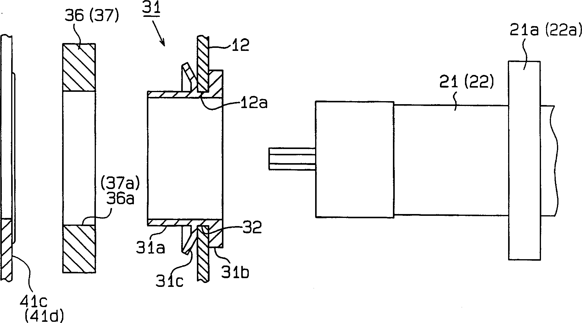
[0088] Such as figure 1 As shown, the box body of the switch 11 includes: a box-shaped main box body 12 with a lower opening and a cover, and a box-shaped bottom box body 13 with an upper opening and a bottom. The lower opening of the main box body 12 is formed by the bottom box. Body 13 is closed. The fastening pressing piece 14 provided on the opening side of the bottom box body 13 is fastened by bolts 16 and nuts 17 relative to the connecting piece 15 provided on the opening side of the main box body 12 . Thereby, the bottom box body 13 can be detachably connected to the main box body 12 . A sealing member 18 is sandwiched between the main box body 12 and the bottom box body 13 , and the sealing member 18 keeps the airtightness of the switch 11 .

[0089] On...


PUM


Abstract

A switch, wherein an encased zero-phase current transformer (36) and a cut-off relay (37) are fitted into the inside edges of both bushings (21, 22). Between each of the zero phase sequence current transformer (36) and the cut-off relay (37) and an unit casing, an elastic pressing element (31c) is provided that presses both the zero phase sequence current transformer (36) and the cut-off relay (37) in the inside direction of the casing. The movement of the zero phase sequence current transformer (36) and the cut-off relay (37) toward the inside of the casing is restricted by an insulating barrier (41). This structure makes it unnecessary to set screws into the inside surface of the casing and improve withstand voltage between the switch and ground.

Description

technical field [0001] The invention relates to a switch having built-in components such as a zero-phase-sequence converter and a disconnecting relay. Background technique [0002] In the past, built-in components for switches such as zero-phase-sequence converters were placed in the fastening cover and inserted into the inner ends of the bushings penetrating and supported on the two side walls of the switch main box body. The fastening cover is inserted into the bolt erected on the side surface of the main box body of the switch, and the nut is fastened on the bolt, thereby fixing the fastening cover on the main box body. However, in the conventional support structure for built-in components for switches, bolts for fixing the built-in components must be provided on the inner side of the main case. As a result, the insulation distance between the tip of the bolt and the electrode portion at the tip of the bushing becomes short, and the withstand voltage between the grounds ...

Claims


Application Information

Patent Timeline
IPC IPC(8): H01H9/00H01H31/00H01H31/02H01H31/28H01H33/02H01H33/04H01H33/53H02B13/02
Inventor 小寺克昌岩本义丰伊藤元
Owner ENERGY SUPPORT CORP
Why Eureka
Try Eureka