


Quick Research
Generate reliable direction feasibility study reports for your R&D in just a few steps.

Technical Q&A
Discover and master advanced knowledge NOW. Basics, ideas, possibilities, all at once.

Find Solutions
As an expert in R&D theories, this can generate solutions to your technical problems instantly.

Evaluate Feasibility
Analyze your overall solution with one click, know your potential R&D risks in advance.

Monitor Landscape
Get weekly tech updates, stay abreast of the latest tech innovations and key insights.
Polymer electrolyte fuel cell
A polymer electrolyte, fuel cell technology, applied in solid electrolyte fuel cells, fuel cells, fuel cell components and other directions, can solve problems such as cost reduction and other advantages
- Summary
- Abstract
- Description
- Claims
- Application Information
AI Technical Summary
Problems solved by technology
Method used
Image

Examples
Embodiment approach 1
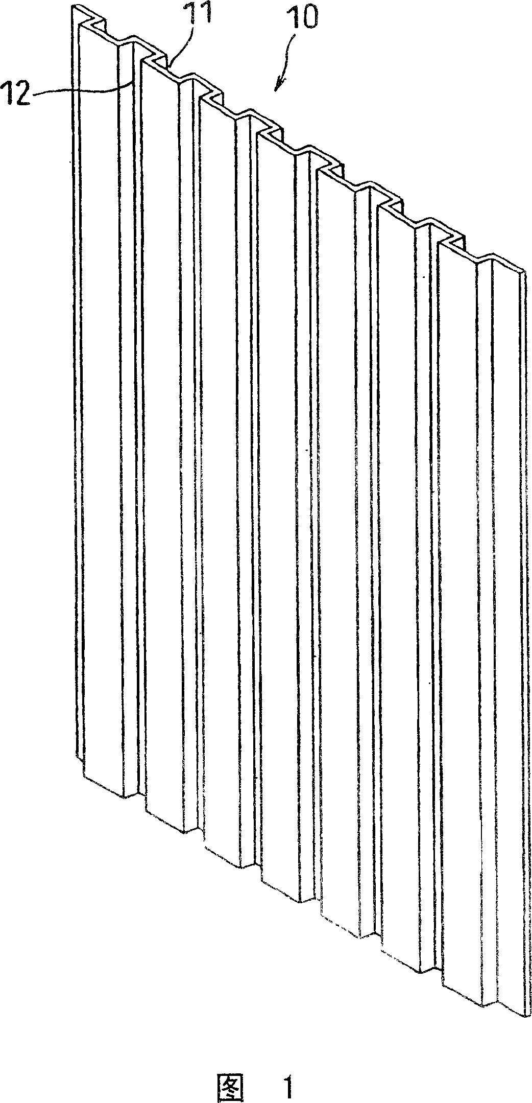
[0054] FIG. 1 shows a corrugated metal plate 10 obtained by press-working a metal plate such as stainless steel. In this embodiment, such a corrugated metal plate is used as it is for the conductive separator. The corrugated metal plate 10 has grooves 11 and protrusions alternately on one surface, and has protrusions and grooves 12 on the other surface corresponding to the grooves 11 and protrusions.
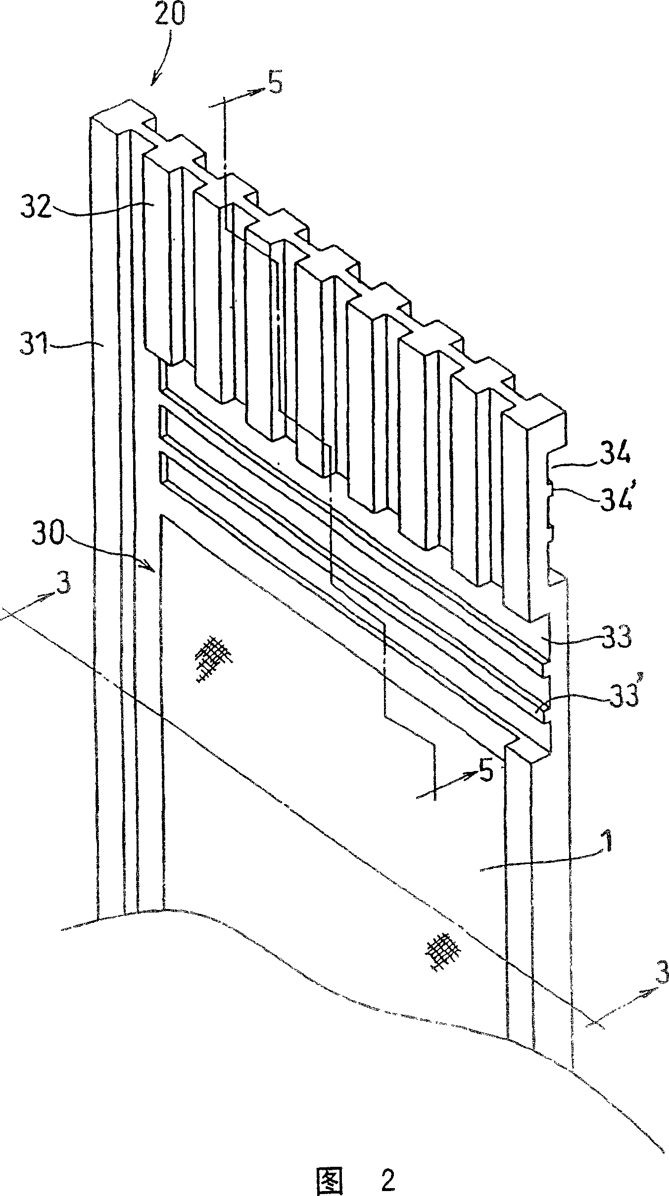
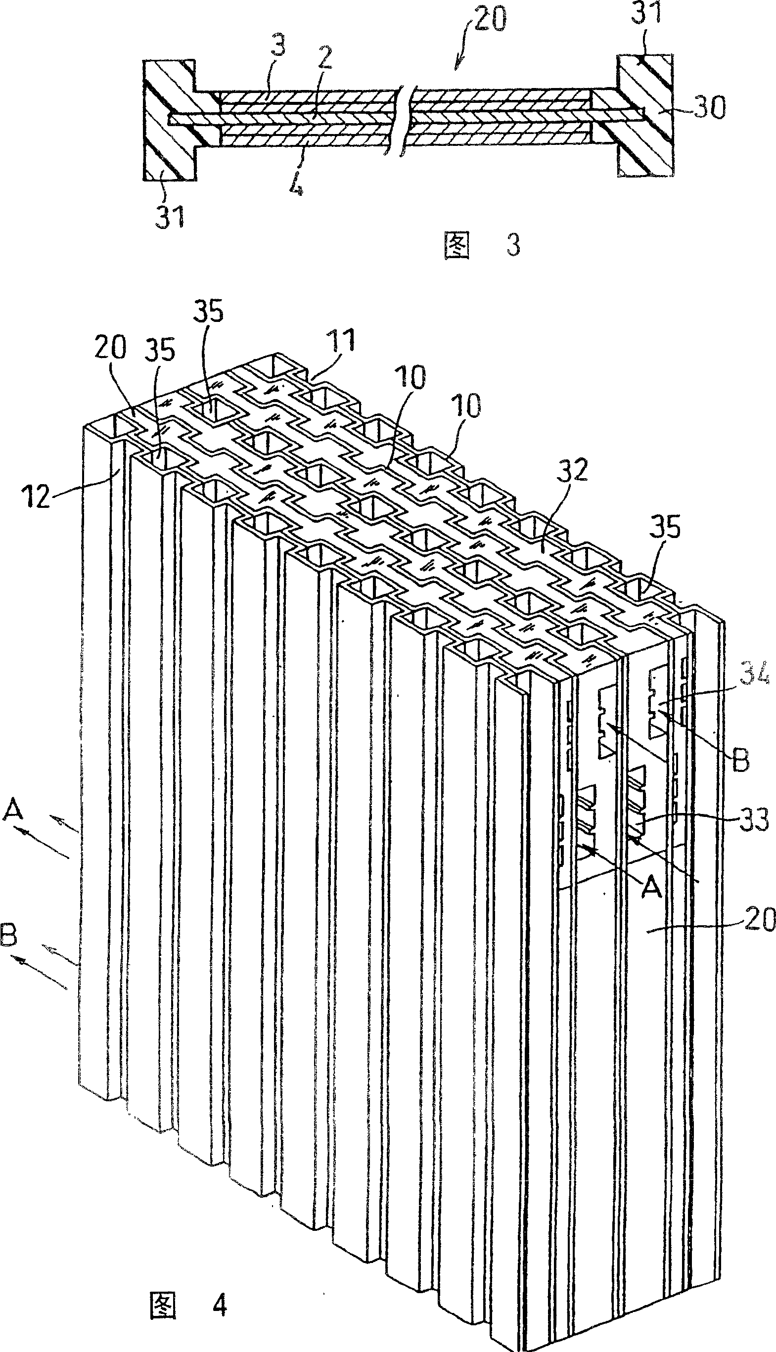
[0055] 2 and 3 show an MEA 20 constituting a galvanic cell stack alternately laminated with conductive separators made of the above-mentioned corrugated metal plates. As shown in FIG. 3, the MEA 20 is composed of a polymer electrolyte membrane 2, an air seal portion 30 composed of a thermoplastic resin or a thermoplastic elastomer integrally covering the peripheral portion of the membrane 2, and a negative electrode 3 bonded to the exposed surface of the membrane 2. The positive electrode 4 constitutes. The negative electrode and the positive electrode consist of a catalyst la...
Embodiment approach 2
[0066] In Embodiment 1, ribs 31 , 32 and the like are provided on the gas seal portion 30 of the MEA in order to prevent gas from leaking between the metal plate 10 and the MEA. In Embodiment 2, it is shown that these rib parts are moved from the gas seal portion 30 to the metal plate 10 side.
[0067] In this embodiment, as shown in FIG. 7 , seals 31 a and 32 a made of the same material as the gas seal are integrally bonded to the metal plate 10 by injection molding or the like to replace the ribs 31 and 32 of the gas seal 30 . The MEA 20a combined with such a conductive separator made of a metal plate has a flat plate shape as shown in FIG. 8 . Also, there are grooves 33a and 34a for inducing gas.
Embodiment approach 3
[0069] The MEA 20b is shown in FIG. 9 . This MEA is different from the MEA shown in FIG. 2 in that a manifold is provided, and has the same structure otherwise. That is, the gas seal portion 30 has a pair of grooves 33 b for guiding the oxidant gas across the negative electrode of the electrode portion 1 , and ribs 32 b closing the ends of the grooves 11 of the metal plate 10 . Similarly, ribs for closing a pair of grooves (corresponding to grooves 34 in FIG. 2 ) for guiding fuel gas and the ends of the grooves 12 of the metal plate 10 are provided on the surface having the positive electrode.
[0070] The gas seal unit 30b has an oxidant gas manifold 37 and a fuel gas manifold 38 on side portions of the oxidant gas guide groove 33b and the fuel gas guide groove, and cooling water manifolds 39 on both ends. The air seal portion 30b also has ribs 31b on the peripheral edge.
[0071] In a galvanic battery using such an MEA, the oxidant gas supplied from one of the pair of mani...
PUM
| Property | Measurement | Unit |
|---|---|---|
| thickness | aaaaa | aaaaa |
| thickness | aaaaa | aaaaa |
| wavelength | aaaaa | aaaaa |
Abstract
Description
Claims
Application Information
 - R&D Engineer
- R&D Manager
- IP Professional
- Industry Leading Data Capabilities
- Powerful AI technology
- Patent DNA Extraction
Browse by: Latest US Patents, China's latest patents, Technical Efficacy Thesaurus, Application Domain, Technology Topic, Popular Technical Reports.
© 2024 PatSnap. All rights reserved.Legal|Privacy policy|Modern Slavery Act Transparency Statement|Sitemap|About US| Contact US: help@patsnap.com