Moving turbine blade

A blade, working technology, applied in the direction of blade support elements, engine elements, machines/engines, etc., can solve the problem of damage to turbine disks, etc.

Inactive Publication Date: 2007-05-02
SIEMENS AG
View PDF4 Cites 0 Cited by
  • Summary
  • Abstract
  • Description
  • Claims
  • Application Information

AI Technical Summary

Problems solved by technology

However, this load can only be increased by a small amount, otherwise there is a risk of damage to the turbine disk

Method used


Image

  • Moving turbine blade
  • Moving turbine blade
  • Moving turbine blade

Examples


Embodiment Construction

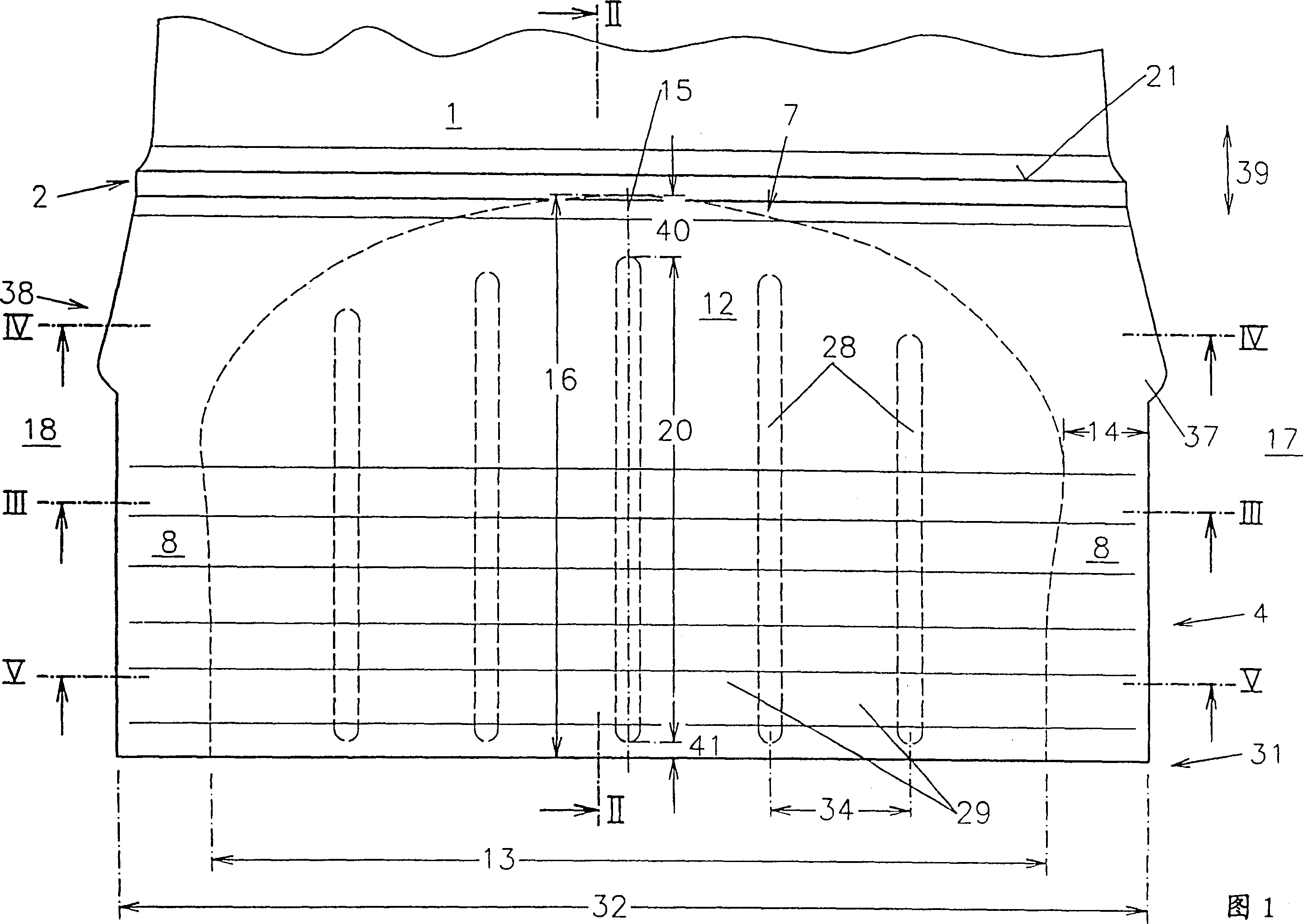
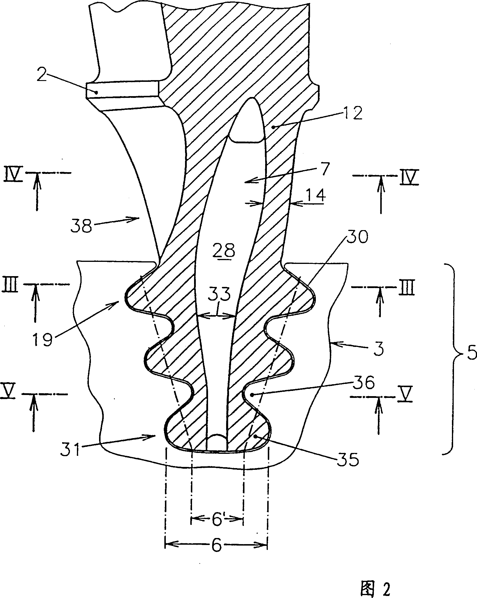
[0024] FIG. 1 shows a turbine blade root 4 as well as a platform 2 and a partial airfoil 1 in radial section. The blade root 4 is inserted into a mortise 30 of the turbine wheel disk 3 and fixed in a form-closed manner by means of the mortise teeth 35 of the blade root 4 and the corresponding teeth 36 on the mortise 30 , as shown in FIG. 2 . The blade root 4, the platform 2 and the airfoil 1 are integrally formed, preferably poured into one body. The side-by-side airfoils 1 provide resistance to the flowing hot gas and change its speed and direction, thereby causing the turbine wheel disk 3 to rotate at a high rotational speed around the disk axis. The centrifugal forces that occur in this case essentially have to be absorbed by the teeth 35 of the blade root 4 and the teeth 36 of the groove 30 . Especially in the case of turbine blades without internal cooling, a large part of the turbine blade is usually solid and thus has a high weight, which places a considerable load on ...


PUM


Abstract

The invention relates to a turbine blade having an internally uncooled blade profile (1) extending from a blade platform (2) to which is connected a blade inserted into a turbine wheel disk (3) A root (4) having a radial section (5) of increasing width (6') towards the blade platform (2). In order to design a turbine rotor blade of this type capable of lengthening the rotor blade profile, the invention proposes that the blade root (4) has a hollowed-out slot (7) opening away from the platform, which slot is a blind hole on the platform side shape ends, and is correspondingly widened in the width (6') increasing region (5) of the blade root (4) according to the size of the blade root section.

Description

technical field [0001] The invention relates to a working blade of a turbine, which has an internally uncooled airfoil, which extends from a blade platform connected to a blade root inserted into a turbine wheel disk, the radial section of the blade root has a The area of ​​increasing width in the direction of the blade platform. Background technique [0002] In order to increase the efficiency of the gas turbine, ie to increase the effective cross section, the profile of the rotor blades of the turbine is made as long as possible, in order thereby to achieve a better utilization of the gas flowing through. However, this lengthening of the leaf shape is limited by various factors. [0003] Due to the lengthening of the airfoil and the resulting increased moving mass, the load on the hub region of the turbine wheel disk is significantly increased, for example due to the effect of centrifugal forces. Attempts have been made to counteract this by increasing the bearing surfac...

Claims


Application Information

Patent Timeline
Patent Type & Authority Patents(China)
IPC IPC(8): F01D5/18F01D5/14
CPCF01D5/081F01D5/3007F01D5/187F01D5/147
Inventor 彼得·蒂曼迈克尔·斯特拉斯伯格德克·安丁
Owner SIEMENS AG
Why Eureka
Try Eureka