Emptying oil cleaning tank diving oil pump

A technology for submersible pumps and warehouse sweeping, which is applied in the direction of pumps, pump devices, non-variable pumps, etc. It can solve the threat to the health and safety of operators, centrifugal pumps do not have gas-liquid mixed transmission, and the layout of loading and unloading pipelines is complicated, etc. problems, to achieve the effect of easy layout and control, compact structure and low noise

Inactive Publication Date: 2006-05-17
ZHEJIANG JIALI TECH
View PDF1 Cites 0 Cited by
  • Summary
  • Abstract
  • Description
  • Claims
  • Application Information

AI Technical Summary

Problems solved by technology

However, the submersible pump of this structure has the following defects in use: 1. Since the submersible pump only uses a centrifugal pump to work, the centrifugal pump does not have the function of gas-liquid mixed transportation, and the oil in the tank car or the ground tank cannot be transported Full output (under normal circumstances, there are still about 200 liters of oil remaining in the tank car), so it can only be used for unloading oil, not for "sweeping"; The oil is completely output, and the vacuum sweeping device must be used when "sweeping the warehouse". This kind of sweeping device needs to be equipped with vacuum equipment and separately arranged pipelines, which makes the pipeline layout of the entire oil loading and unloading complex, high equipment maintenance costs, and difficult operation. Large; what is more important is that a large amount of oil and gas will be discharged to the atmosphere when the vacuum sweeping device is used to sweep the warehouse, which not only pollutes the environment, but also poses safety hazards, and requires the sweeping operator to hold the sweeping hose at the top of the tank car. This also poses a great threat to the personal health and safety of operators, especially when unloading and sweeping toxic volatile solvents, the environmental pollution and the harm to operators are even greater

Method used


Image

  • Emptying oil cleaning tank diving oil pump
  • Emptying oil cleaning tank diving oil pump

Examples


Embodiment Construction

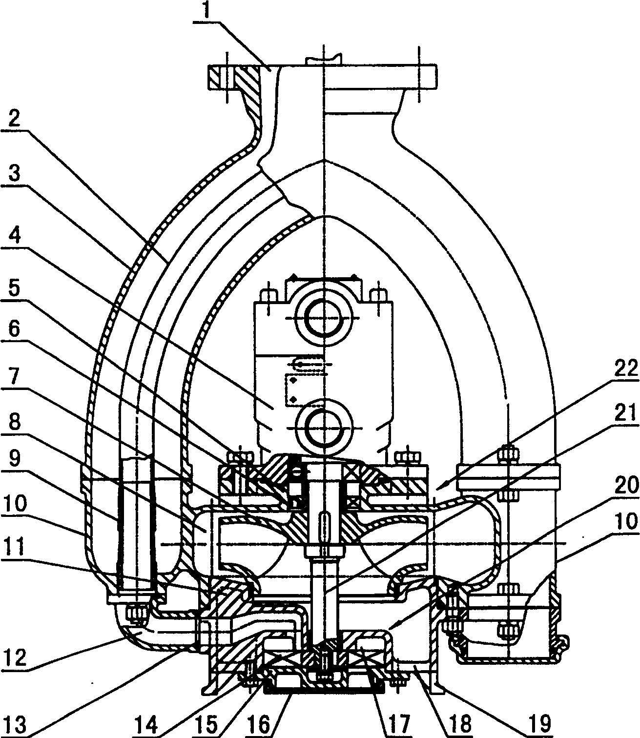
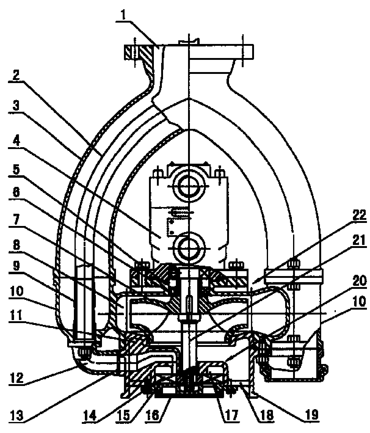
[0013] As shown in the figure, the present invention mainly includes a centrifugal pump 22, a vortex pump 20, a hydraulic motor 4 and an oil delivery pipe 3, wherein the hydraulic motor 4 is connected to the upper end of the centrifugal pump body 5, and the upper end of the vortex pump body 11 is embedded in the centrifugal pump body. The lower end of the body 5 is connected with the centrifugal pump body by bolts, thereby forming a centrifugal pump pressure chamber 8 in the centrifugal pump body; the vortex pump body is provided with a passage 18 for oil to enter the centrifugal pump pressure chamber, and the lower end of the passage It is the suction port of the centrifugal pump; the hydraulic motor shaft 21 passes through the centrifugal pump pressure chamber 8 and extends into the vortex pump pressure chamber 17, and the centrifugal pump impeller 7 located in the centrifugal pump pressure chamber is connected with the vortex pump impeller 14 located in the vortex pump pressu...


PUM


Abstract

The invention relates to an oil unloading and sweeping submersible pump. It includes a hydraulic motor and a centrifugal pump below it. The impeller of the centrifugal pump is connected to the shaft of the hydraulic motor. A vortex pump is arranged below the centrifugal pump. The impeller of the vortex pump is also connected to the shaft of the hydraulic motor. The centrifugal pump has a centrifugal A pump discharge port, the vortex pump has a vortex pump discharge port. It can thoroughly "sweep the warehouse", and even absorb the residual oil on the oil pipeline; avoid a large amount of oil and gas to be discharged into the atmosphere, greatly reducing environmental pollution; during operation, the operator stays away from the top port of the tanker, which can Effectively reduce and avoid potential safety hazards.

Description

【Technical field】 [0001] The invention relates to a fluid machine, in particular to an oil unloading and sweeping submersible pump. 【Background technique】 [0002] At present, the train tank cars and ground tanks used for transporting or storing light oil materials (including light chemical solvents) in my country are not allowed to be equipped with lower and unloading ports, and the top loading and top unloading methods are used to load and unload oil materials. In order to solve the "air resistance" problem (especially in high temperature and plateau areas where oil is easy to vaporize), the ideal oil loading and unloading device is a pneumatic or hydraulic submersible pump. This submersible pump only has a centrifugal pump. In the tank, and its oil discharge port is connected with the suction port of the liquid loading and unloading arm, the impeller of the centrifugal pump is driven to rotate through a pneumatic or hydraulic device, and centrifugal force is generated to ou...

Claims


Application Information

Patent Timeline
Patent Type & Authority Patents(China)
IPC IPC(8): F04D13/14
Inventor 龚政尧钱永康胡志恩
Owner ZHEJIANG JIALI TECH
Why Eureka
Try Eureka