
Over-heat and over-current protecting unit

An overcurrent protection and overheating technology, applied in the direction of the protection switch operation/release mechanism, etc., can solve the problem of miniaturizing the overall volume of the thermal-magnetic circuit breaker, and achieve the effect of miniaturizing the overall volume

Inactive Publication Date: 2004-06-02
常熟开关制造有限公司
View PDF4 Cites 0 Cited by
  • Summary
  • Abstract
  • Description
  • Claims
  • Application Information

AI Technical Summary

Problems solved by technology

Therefore, in the above-mentioned prior art, there is no technical information that integrates the heating element and the current limiting element to reduce the overall volume of the thermal magnetic circuit breaker.

Method used


Image

  • Over-heat and over-current protecting unit
  • Over-heat and over-current protecting unit
  • Over-heat and over-current protecting unit

Examples


Embodiment Construction

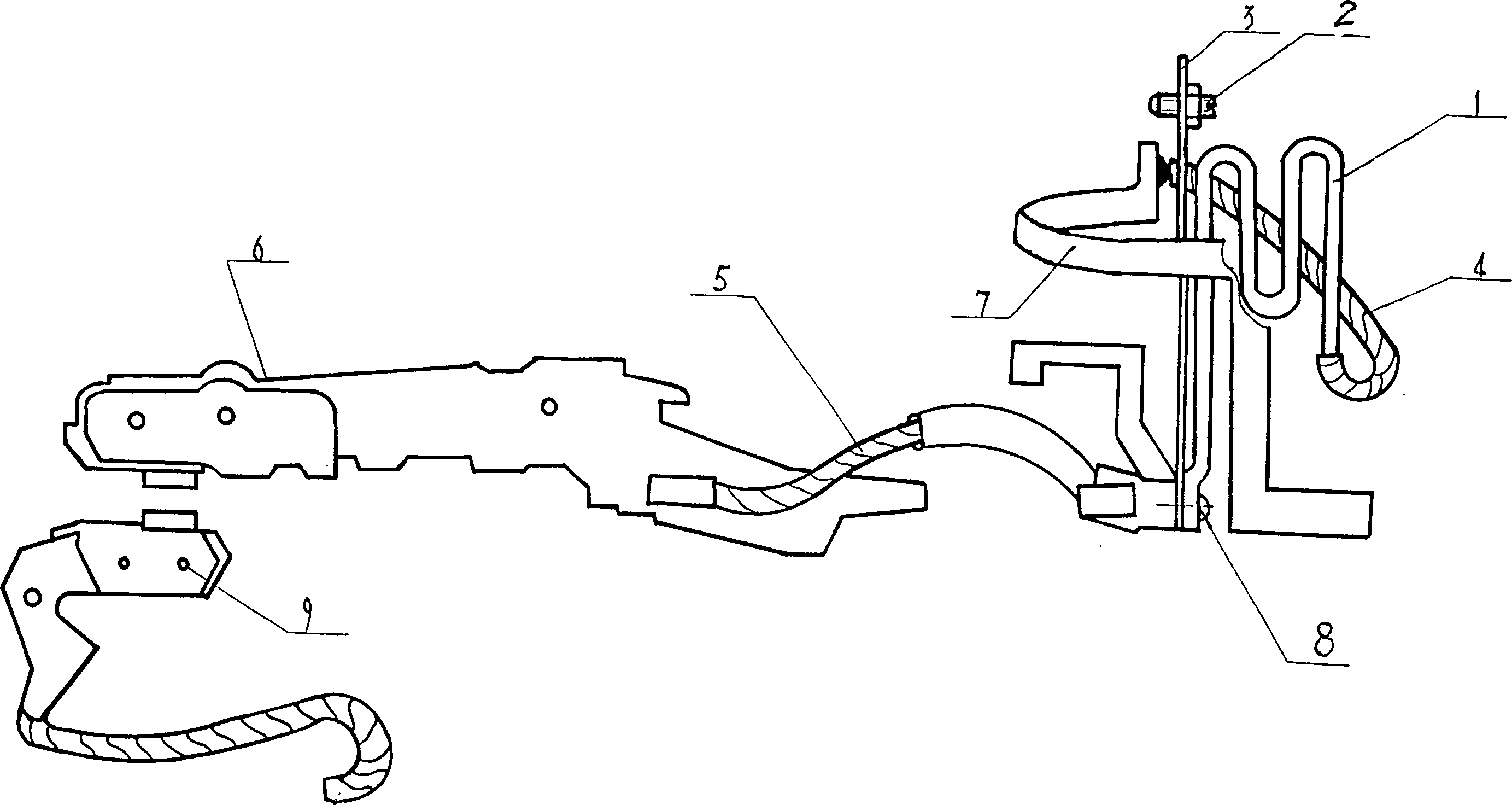
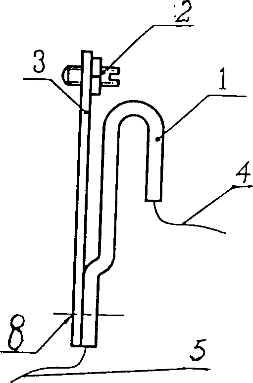
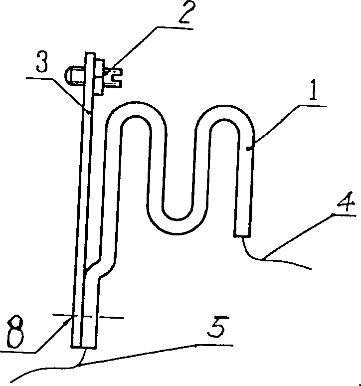
[0012] One end of the current limiting and heating element 1 of the present invention is bent. Such as figure 2 , image 3 As shown, one end of the current-limiting and heating element 1 is bent into a U-shape or an S-shape, or it can be bent into two, three or more U-shape or S-shape, and the degree of bending depends on The length L and the space allowed by the circuit breaker can further save the space of the circuit breaker.

[0013] The two ends of the current limiting and heating element 1 of the present invention are bent. Such as Figure 4 As shown, the two ends of the current-limiting and heating element 1 are bent into a U-shape or an S-shape, and can also be bent into two, three or more U-shape or S-shape, and the degree of bending is It depends on the length L and the space allowed by the circuit breaker, which can further save the space of the circuit breaker.

[0014] The current-limiting and heating element 1 of the present invention is made of materials w...


PUM


Abstract

An over-heat and over-current protecting unit for thermomagnetic circuit breaker is composed of current elimiting element, exothermic element, bimetal element, and trip regulating element. It feature that the current limiting element and the exothermic element are integrated into one whole for smaller size.

Description

technical field [0001] The invention relates to an overheat and overcurrent protection unit, in particular to an overheat and overcurrent protection unit used in a thermomagnetic circuit breaker, which belongs to an overcurrent protection component of an electrical appliance. Background technique [0002] The overheating and overcurrent protection unit of the existing thermal magnetic circuit breaker (such as Figure 5 shown) is composed of a current limiting element 1, a heating element 2 and a bimetallic element 3. The heating element 2 is made of a material such as a pure copper strip or a stainless steel strip or a tin bronze strip or a resistance alloy strip with a certain resistivity, and is mounted on it The bimetal element 3 is fixed with the rivet 4, and then connected to the circuit of the upper contact 6 of the tripping mechanism of the thermal magnetic circuit breaker by the wire 5. When the current in the circuit is overloaded, the heat generated by the heating ...

Claims


Application Information

Patent Timeline
Patent Type & Authority Patents(China)
IPC IPC(8): H01H71/14H01H71/16
Inventor 杨学军王炯华陈志刚周喜刚张洵初吴燕吴海霞
Owner 常熟开关制造有限公司
Learn More