
Electric pump and failure state notification method for electric pump

A fault state, electric pump technology, applied in the direction of motor control, electrical components, control systems, etc., can solve the problem of increasing the frequency of the pulse signal, and achieve the effect of suppressing the increase in burden

Pending Publication Date: 2022-08-05
YAMADA SEISAKUSHO KK
View PDF1 Cites 0 Cited by
  • Summary
  • Abstract
  • Description
  • Claims
  • Application Information

AI Technical Summary

Problems solved by technology

In the electric pump described in Patent Document 1, when the rotational speed of the motor is 160 rpm or less, the frequency of the pulse signal is set to 4 Hz (although it is not in a stopped state), and when the rotational speed of the motor exceeds 160 rpm, As the speed of the motor increases, the frequency of the pulse signal increases functionally

Method used


Image

  • Electric pump and failure state notification method for electric pump
  • Electric pump and failure state notification method for electric pump
  • Electric pump and failure state notification method for electric pump

Examples


Embodiment Construction

[0035] Hereinafter, embodiments of the electric pump and the failure state notification method of the electric pump of the present invention will be described.

[0036]

[0037] figure 1 It is a figure which shows an example of the structure of the electric pump 1 etc. of 1st Embodiment.

[0038] exist figure 1In the illustrated example, the electric pump 1 includes a pump 11 , a motor 12 , a motor drive unit 13 , and a control unit 14 .

[0039] The pump 11 performs pressure feeding and the like of a fluid (medium) such as water, oil, and fuel. The motor 12 drives the pump 11 .

[0040] The motor drive unit 13 is, for example, an inverter circuit or the like, and includes a switching element 13A and a rotational speed information processing unit 13B. The switching element 13A is, for example, a semiconductor switching element such as an IGBT (Insulated Gate Bipolar Transistor) and a MOSFET (Metal-Oxide-Semiconductor Field Effect Transistor). The motor drive unit 13 dri...


PUM


Abstract

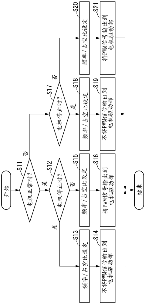
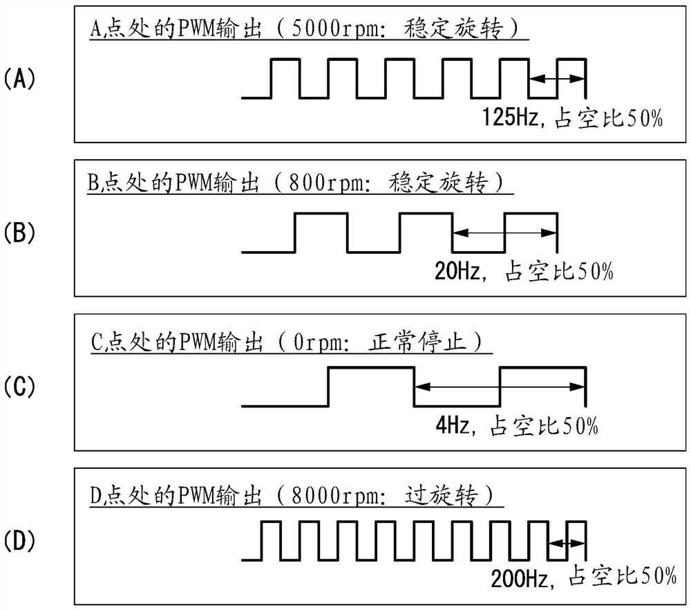
An electric pump is provided with a pump, a motor that drives the pump, a motor drive unit that has a switching element and drives the motor using power output from the switching element, and a control unit that outputs a PWM signal for driving the switching element to the motor drive unit. The PWM signal output from the control unit is used for monitoring the state of the motor, and when the motor is abnormally stopped in the electric pump, the control unit sets the frequency of the PWM signal used for monitoring the state of the motor to a frequency outside the frequency domain used when the motor is normal.

Description

technical field [0001] The present invention relates to an electric pump and a fault state notification method of the electric pump. [0002] This application claims priority based on US Provisional Application No. 62 / 958313 filed on January 8, 2020, the content of which is incorporated herein by reference. Background technique [0003] Patent Document 1 describes an electric pump including a control unit that outputs a pulse signal indicating the rotational state of the motor. [0004] In the electric pump described in Patent Document 1, a motor drives a pump connected to the motor, and a drive unit including a plurality of semiconductor switching elements drives the motor with a three-phase AC voltage. An input signal for driving the motor is input from an ECU (Electronic Control Unit) to the control portion of the electric pump. The control unit of the electric pump outputs a drive signal for driving the motor to the drive unit based on an input signal input from the EC...

Claims


Application Information

Patent Timeline
Patent Type & Authority Applications(China)
IPC IPC(8): H02P29/024
CPCH02P29/024H02P27/085F04D15/0077F04D15/0281H02P6/08
Inventor 久保田庆樱井英之岩崎拓弥田沼树伊藤圣人
Owner YAMADA SEISAKUSHO KK
Learn More