Multi-machine phase synchronization system and method based on optical fiber transmission

A technology of optical fiber transmission and phase synchronization, which is applied in the field of multi-machine systems, can solve problems such as inability to accurately track phase changes, unsatisfactory real-time performance, and complex circuits, and achieve good synchronization performance and scalability, fewer bits, and more The effect of small number of machines

Active Publication Date: 2022-08-05
ILD ELECTRONICS CO LTD
View PDF4 Cites 0 Cited by
  • Summary
  • Abstract
  • Description
  • Claims
  • Application Information

AI Technical Summary

Problems solved by technology

At present, there are mainly two methods for phase synchronization in multi-machine systems. One is to transmit the zero-crossing signal. The master device sends a synchronous zero-crossing signal to the slave device, and the slave device receives the synchronous zero-crossing signal. Phase synchronization has strong real-time performance, but the accuracy is not high. It is synchronized once in a cycle, especially when the frequency changes, the phase change cannot be accurately tracked, and a phase mutation will occur; the other is the reference source phase-locked technology, which will The analog reference source is sent to the slave device, and the slave device discriminates its frequency, locks the phase, and obtains the phase information
The accuracy is high, and it can track the change of the phase, but the implementation circuit is relatively complicated, and the real-time performance cannot meet the requirements, and there is a certain delay effect

Method used


Image

  • Multi-machine phase synchronization system and method based on optical fiber transmission
  • Multi-machine phase synchronization system and method based on optical fiber transmission
  • Multi-machine phase synchronization system and method based on optical fiber transmission

Examples


Embodiment Construction

[0030] The embodiments of the present invention are described in detail below. This embodiment is implemented on the premise of the technical solution of the present invention, and provides a detailed implementation manner and a specific operation process, but the protection scope of the present invention is not limited to the following implementation. example.

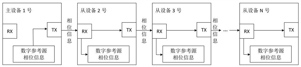
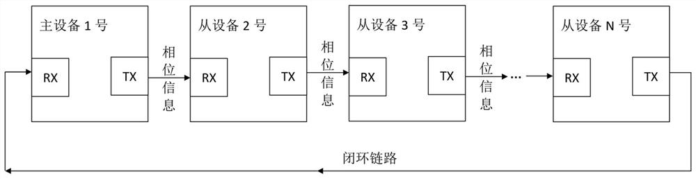
[0031] The invention discloses a multi-machine phase synchronization system based on optical fiber transmission, such as figure 1 As shown, it includes several (at least two) devices to form a multi-machine system, and each device has an optical fiber transmitting interface (TX) and an optical fiber receiving interface (RX), wherein the receiving port of No. N-1 equipment It is connected to the transmitting port of No. N-2 equipment, the transmitting port of No. N-1 equipment is connected to the receiving port of No. N equipment, and N is the number of equipment. One device in the system is the master device, and the...


PUM


Abstract

The invention discloses a multi-machine phase synchronization system and method based on optical fiber transmission, the system comprises a master device and a plurality of slave devices, an optical fiber transmitting interface of the master device is connected with an optical fiber receiving interface of one slave device, and the slave device connected with the master device is sequentially connected with other slave devices in series. The master device transmits the phase information of the digital reference source of the device as a system synchronization phase signal to the slave device connected with the master device, and the slave device uses the received system synchronization phase signal as the digital reference source phase of the device; the system synchronous phase signal is sent to the slave device connected with the slave device optical fiber emission interface through the optical fiber emission port, and when the last slave device is connected with the master device, the master device and the slave device form a closed-loop communication test. Synchronous phase code values are transmitted in real time in high-speed optical fiber communication, accuracy is high, phase changes can be tracked in real time, and good synchronization performance and expansibility are achieved in a multi-machine power system.

Description

technical field [0001] The invention relates to the technical field of multi-machine systems, in particular to a multi-machine phase synchronization system and method based on optical fiber transmission. Background technique [0002] Multi-machine phase synchronization is widely used in power system. In the multi-phase system, the slave device realizes the phase difference to the master device on the basis of synchronizing the phase of the master device; the multi-machine power supply device also inverts the phase by adding a 180-degree phase difference after synchronizing the phase, and then realizes the boost in series. The real-time performance and accuracy of multi-machine phase synchronization are the two main points in the application. At present, there are two main methods for phase synchronization in the multi-machine system. One is to transmit the zero-crossing signal. The master device sends the synchronous zero-crossing signal to the slave device. The slave devic...

Claims


Application Information

Patent Timeline
IPC IPC(8): H04B10/25H04B10/40H04B10/075
CPCH04B10/25H04B10/40H04B10/075H04B10/0773H04B10/2507
Inventor 不公告发明人
Owner ILD ELECTRONICS CO LTD
Why Eureka
Try Eureka