Square steel blanking device for forging of petrochemical mining casing head

A casing head, petrochemical technology, applied in household refrigeration devices, forging/pressing/hammer devices, applications, etc., can solve the problems of high surface temperature, inconvenient transportation, affecting production efficiency, etc., and achieve the effect of accelerating heat dissipation and cooling

Pending Publication Date: 2022-08-05
CHONGQING YONGCHUAN DISTRICT YIRUI MACHINERY
View PDF7 Cites 0 Cited by
  • Summary
  • Abstract
  • Description
  • Claims
  • Application Information

AI Technical Summary

Problems solved by technology

[0005] Aiming at the deficiencies in the prior art, the present invention provides a square steel blanking device for casing head forging in petrochemical mining, in order to solve the problem that the surface temperature of the forging is relatively high after being forged by a forging machine. The transfer is very inconvenient, and after the transfer, the next process cannot be carried out because the temperature is too high, which will affect the production efficiency

Method used


Image

  • Square steel blanking device for forging of petrochemical mining casing head
  • Square steel blanking device for forging of petrochemical mining casing head

Examples


Embodiment 1

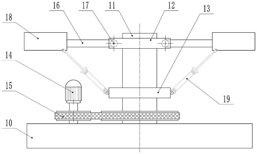
[0023] basically as figure 1 As shown, the square steel blanking device used for forging casing heads for petrochemical mining includes a workbench 10, on which a main shaft 11 is vertically rotatably connected, and on the main shaft 11 are coaxially fixed with a first mounting plate 12 and The second mounting plate 13, wherein the first mounting plate 12 is located above the second mounting plate 13, and a drive unit for driving the main shaft 11 to rotate is provided on the worktable 10; in this embodiment, the drive unit includes a reduction motor 14 and a belt transmission mechanism 15, wherein the belt transmission mechanism 15 includes a driving pulley, a driven pulley and a belt, the driving pulley is coaxially fixed on the output shaft of the deceleration motor 14, and the driven pulley is coaxially fixed on the main shaft 11, and is located in the first Below the two mounting plates 13, the belt connects the driving pulley and the driven pulley.

[0024] In this embo...

Embodiment 2

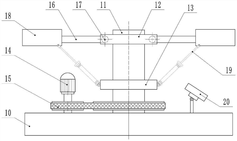
[0030] The difference from Example 1 is that the combination figure 2 As shown, in this embodiment, a cooling fan 20 is also provided on the workbench 10, wherein the cooling fan 20 is located on the connecting line between the main shaft 11 and the material box, and the air outlet of the cooling fan 20 is inclined toward the side of the receiving hopper 18 Setting, the angle of inclination is 30°~40°.

[0031] In this way, when the high-temperature forging is transported, the air flow generated by the cooling fan 20 can act on the bottom of the hopper 18, and since the air outlet of the cooling fan 20 is inclined in this embodiment, it can reduce the drop of the high-temperature forging during the transporting process. The metal chips enter into the cooling fan 20 .


PUM


Abstract

The invention belongs to the technical field of forging equipment, and particularly discloses a square steel blanking device for forging a petrochemical mining casing head, which comprises a workbench, a main shaft is vertically and rotatably connected to the workbench, a driving unit for driving the main shaft to rotate is arranged on the workbench, a plurality of material receiving rods are hinged to the main shaft, and the material receiving rods are arranged on the workbench. A plurality of material receiving rods are distributed in the circumferential direction of the main shaft at equal intervals, a material receiving hopper is fixed to the ends of the material receiving rods, an electric air cylinder is hinged between the main shaft and the bottom of the material receiving hopper, a cylinder body of the electric air cylinder is hinged to the second mounting disc, and a piston rod of the electric air cylinder is hinged to the bottom of the material receiving hopper. By the adoption of the scheme, the problems that after a forging piece is forged and pressed through a forging machine, the surface temperature is high, transferring after forging is very inconvenient, the next working procedure cannot be conducted due to the too high temperature after transferring, and therefore the production efficiency is affected can be solved.

Description

technical field [0001] The invention belongs to the technical field of forging equipment, and particularly relates to a square steel blanking device used for forging casing heads for petrochemical mining. Background technique [0002] Forging is a common process in mechanical processing. In order to achieve certain characteristics, the workpiece needs to be forged at high temperature to obtain such properties; while forging is a kind of metal blank that uses forging machinery to apply pressure to make it plastic. Deformation to obtain a workpiece with certain mechanical properties, certain shape and size. [0003] Forging is one of the two major components of forging (forging and stamping). Through forging, defects such as as-cast looseness generated in the metal smelting process can be eliminated, and the microstructure can be optimized. The mechanical properties are generally better than those of castings of the same material. For important parts in related machinery with...

Claims


Application Information

Patent Timeline
Patent Type & Authority Applications(China)
IPC IPC(8): B21J13/08F25D1/00
CPCB21J13/08F25D1/00Y02P20/10
Inventor 王明安王文革郭平
Owner CHONGQING YONGCHUAN DISTRICT YIRUI MACHINERY
Why Eureka
Try Eureka