Refrigeration cycle device
A refrigeration cycle and control device technology, used in refrigerators, refrigeration and liquefaction, irreversible cycle compressors, etc., can solve problems such as performance degradation and scroll damage, and achieve the effect of inhibiting damage and inhibiting the increase of circulation volume.
- Summary
- Abstract
- Description
- Claims
- Application Information
AI Technical Summary
Problems solved by technology
Method used
Image

Examples
Embodiment approach 1
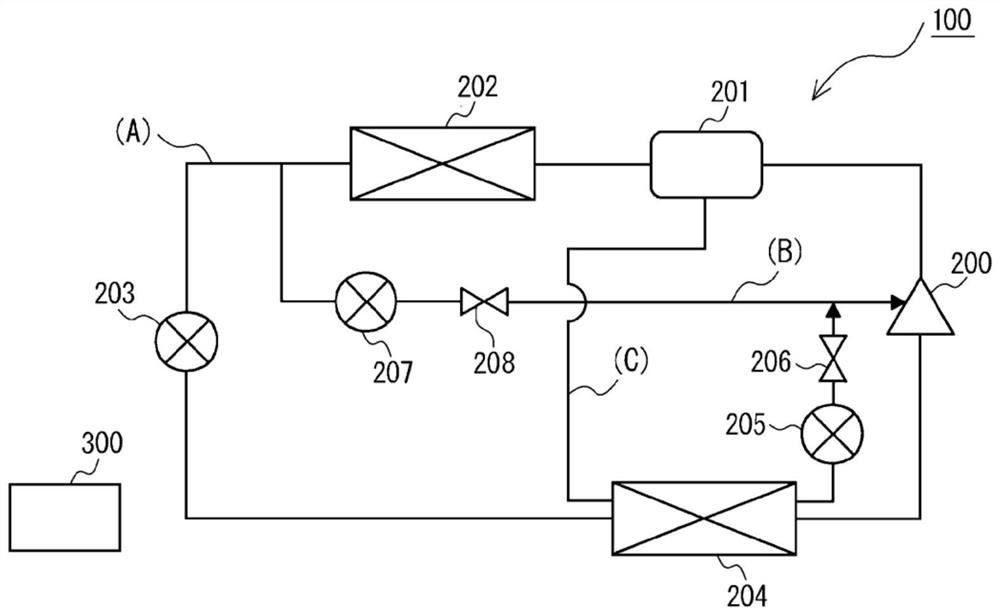
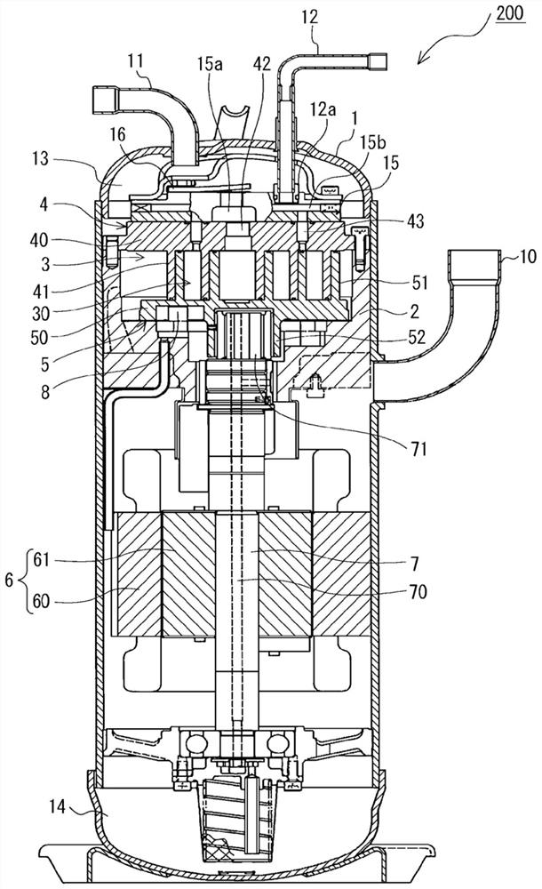
[0016] figure 1 It is a refrigerant circuit diagram of the refrigeration cycle apparatus which concerns on Embodiment 1. figure 2 It is a schematic longitudinal cross-sectional view showing a scroll compressor, which is a constituent element of the refrigeration cycle apparatus according to the first embodiment. The refrigeration cycle apparatus according to Embodiment 1 is used for, for example, an air conditioner, a refrigerating apparatus, a refrigerator, a freezer, a vending machine, or a hot water supply apparatus. like figure 1 As shown, the refrigeration cycle apparatus includes a refrigerant circuit 100 including a main circuit A, a refrigerant injection circuit B, and an oil injection circuit C.
[0017] like figure 1 as well as figure 2 As shown, the main circuit A includes a scroll compressor 200 having a compression chamber 30 for compressing refrigerant and an injection pipe 12 connected to the compression chamber 30, an oil separator 201, a first heat excha...
Embodiment approach 2
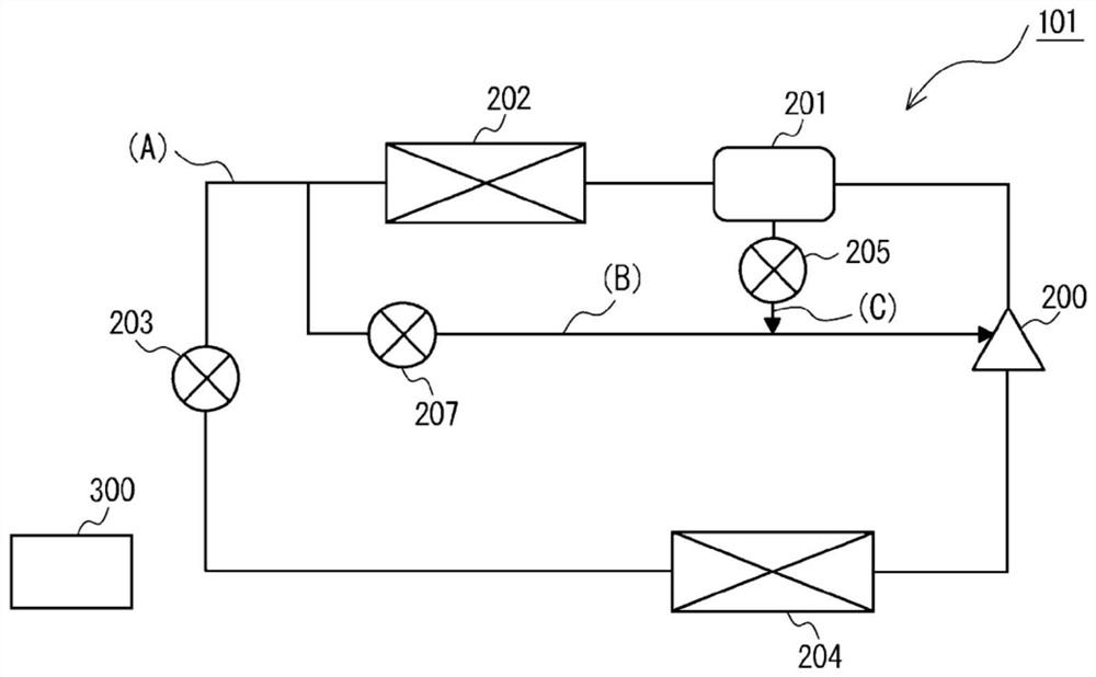
[0044] Next, based on image 3 A refrigeration cycle apparatus according to Embodiment 2 will be described. image 3 It is a refrigerant circuit diagram of the refrigeration cycle apparatus which concerns on Embodiment 2. However, the same reference numerals are attached to the same structures as those of the refrigeration cycle apparatus described in Embodiment 1, and the descriptions thereof are appropriately omitted.
[0045] like image 3 As shown, the refrigeration cycle apparatus according to Embodiment 2 includes a refrigerant circuit 101 including a main circuit A, a refrigerant injection circuit B, and an oil injection circuit C.
[0046] The main circuit A is configured by connecting the scroll compressor 200 , the oil separator 201 , the first heat exchanger 202 , the decompression device 203 , and the second heat exchanger 204 through piping in this order, and circulates the refrigerant. The first heat exchanger 202 in the second embodiment functions as a conden...
Embodiment approach 3
[0053] Next, based on Figure 4 A refrigeration cycle apparatus according to Embodiment 3 will be described. Figure 4It is a refrigerant circuit diagram of the refrigeration cycle apparatus which concerns on Embodiment 3. FIG. However, the same reference numerals are attached to the same structures as those of the refrigeration cycle apparatuses described in Embodiments 1 and 2, and descriptions thereof are omitted as appropriate.
[0054] The refrigerant circuit 102 of the refrigeration cycle apparatus according to the third embodiment is characterized in that, in addition to the configuration of the second embodiment, an oil return pipe for bypassing the oil separator 201 and the suction side of the scroll compressor 200 is provided. 209 structure. The oil return pipe 209 is provided with a third control valve 210 , and the third control valve 210 is controlled by the control device 300 to adjust the flow rate of oil flowing in the oil return pipe 209 . The third control...
PUM
 Abstract
Description
Claims
Application Information
 - R&D
- Intellectual Property
- Life Sciences
- Materials
- Tech Scout
- Unparalleled Data Quality
- Higher Quality Content
- 60% Fewer Hallucinations
Browse by: Latest US Patents, China's latest patents, Technical Efficacy Thesaurus, Application Domain, Technology Topic, Popular Technical Reports.
© 2025 PatSnap. All rights reserved.Legal|Privacy policy|Modern Slavery Act Transparency Statement|Sitemap|About US| Contact US: help@patsnap.com