
Permanent magnet motor mounting shell with heat dissipation structure

A permanent magnet motor and heat dissipation structure technology, which is applied in the direction of motors, electromechanical devices, casings/covers/supports, etc., can solve the problem of excessive heat in the motor, and achieve the effect of increasing the amount of atomized water and efficient heat dissipation , The effect of increasing the atomization effect

Pending Publication Date: 2022-08-02
宋国永
View PDF1 Cites 0 Cited by
  • Summary
  • Abstract
  • Description
  • Claims
  • Application Information

AI Technical Summary

Problems solved by technology

[0004] In this solution, the heat is passively dissipated to the surroundings and then discharged, so that there is still a lot of heat around the motor. Although this method has a certain cooling effect, the actual motor is still at a higher level. temperature in the working environment, so how to solve this problem needs to be considered by us

Method used


Image

  • Permanent magnet motor mounting shell with heat dissipation structure
  • Permanent magnet motor mounting shell with heat dissipation structure
  • Permanent magnet motor mounting shell with heat dissipation structure

Examples


Embodiment approach

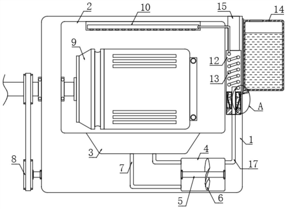
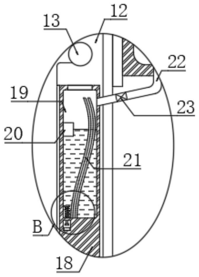
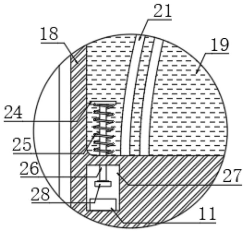
[0029] As an embodiment of the present invention, it also includes an automatic water adding mechanism. The automatic water adding mechanism includes a water storage tank 14 installed on the right side of the housing 1. The inner bottom of the water storage tank 14 communicates with the top space of the annular cavity 19 through the downpipe 22. A trigger cavity 27 is arranged in the chemical box 18, the touch delay switch 11 is installed at the inner bottom of the trigger cavity 27, and a contact block 28 is arranged in the trigger cavity 27. In actual use, the contact block 28 needs to be grounded, thereby After the touch delay switch 11 is touched, the effect of delaying power off is realized. The upper end of the contact block 28 is fixedly connected with a connecting rod 26, and the upper end of the connecting rod 26 extends into the annular cavity 19, and is fixedly connected with the lower pressing plate 24. The lower end of the pressing plate 24 is elastically connected...


PUM


Abstract

The invention discloses a permanent magnet motor installation shell with a heat dissipation structure, which comprises a shell body, an installation cavity is arranged in the shell body, a motor main body is installed in the installation cavity, an air suction groove is formed in the lower end of the installation cavity, a rectangular cavity and a heat dissipation cavity are arranged in the shell body, the heat dissipation cavity is located on the right side of the installation cavity, and the air suction groove is formed in the right side of the rectangular cavity. The rectangular cavity is located below the mounting cavity, and a ventilation opening is formed in the inner top of the heat dissipation cavity. A rotating shaft is rotatably connected between the inner walls of the left side and the right side of the rectangular cavity, a plurality of axial flow blades are arranged on the side wall of the rotating shaft, the left end of the rotating shaft extends to the outside, and the tail end of an output shaft of the motor body extends to the outside. According to the shell, the temperature of a motor in the shell body is continuously brought to the spiral position for heat dissipation in an active heat dissipation mode, water can be atomized in cooperation with a plurality of vibration sheets, then the water is rapidly evaporated in the heat dissipation cavity to absorb heat, and heat dissipation is further improved.

Description

technical field [0001] The invention relates to the field of permanent magnet motor heat dissipation, in particular to a permanent magnet motor installation casing with a heat dissipation structure. Background technique [0002] Motor refers to an electromagnetic device that realizes electric energy conversion or transmission according to the law of electromagnetic induction, and is widely used in industrial production and life. The heat dissipation of the motor is only by adding a heat dissipation plate to absorb and discharge the heat of the motor. However, because the air velocity around the heat dissipation plate is usually slow, the heat absorbed by the heat dissipation plate cannot be discharged in time; [0003] To this end, the Chinese invention patent application number "CN202111206691.7" discloses a motor casing and a motor, which are used for fixing and dissipating heat of the motor, including a ring groove on one side outer wall of the casing, and a cover body di...

Claims


Application Information

Patent Timeline
Patent Type & Authority Applications(China)
IPC IPC(8): H02K5/20H02K9/06H02K5/18H02K7/10H02K9/20H02K9/22H02K9/19
CPCH02K5/207H02K9/06H02K5/18H02K7/10H02K9/20H02K9/227H02K9/225H02K9/19Y02T10/64
Inventor 宋国永
Owner 宋国永
Learn More