
Adjustable plant lamp

A plant lamp, adjustable technology, applied in botany equipment and methods, lighting auxiliary devices, applications, etc., can solve the problems that it is difficult to meet all plant growth needs, fix a single light, and have different requirements for light wavelength and intensity. Good protection effect, good light concentrating effect, and effect of improving utilization rate

Pending Publication Date: 2022-07-29
深圳市雅瑞安光电有限公司
View PDF0 Cites 0 Cited by
  • Summary
  • Abstract
  • Description
  • Claims
  • Application Information

AI Technical Summary

Problems solved by technology

[0004] The purpose of the present invention is to provide an adjustable plant light to solve the above-mentioned background technology. Because the existing plant growth light usually only has a fixed and single light, but different plants have different requirements for light wavelength and intensity in the indoor planting process. , so a plant growth lamp is difficult to meet the growth needs of all plants

Method used


Image

  • Adjustable plant lamp
  • Adjustable plant lamp
  • Adjustable plant lamp

Examples


Embodiment example 1

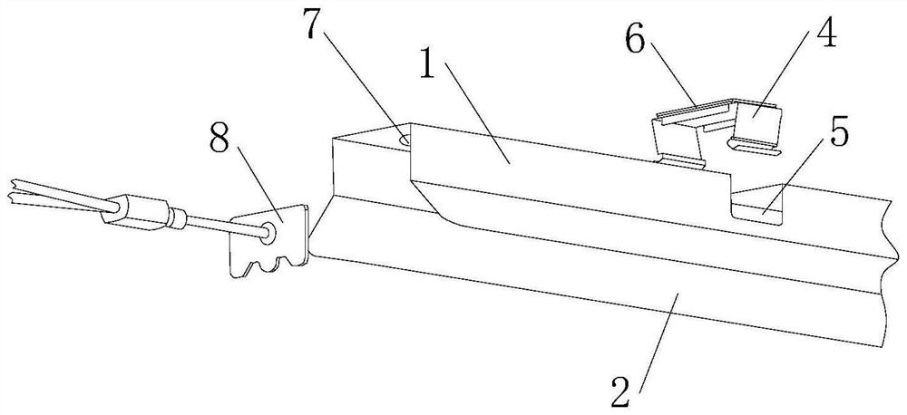
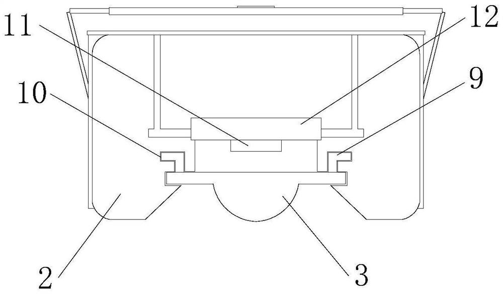
[0036] see Figure 1-2 , an adjustable plant lamp, comprising: a plant lamp housing 1, two sides below the plant lamp housing 1 are connected with a reflector 2, both ends of the plant lamp housing 1 are installed with sealing end caps 8, the sealing end The cover 8 is symmetrically distributed with respect to the vertical centerline of the plant lamp housing 1, and the sealing end cover 8 is fixedly connected with the plant lamp housing 1; It can play a better protective effect and prevent dust or water vapor from entering the grow lamp housing 1; the lamp tube fixing clip 4 is installed on both sides above the grow lamp housing 1, and the lamp tube fixing clip 4 is connected to the grow lamp housing. The connection of 1 is provided with a fixing slot 5, and the lamp tube fixing clip 4 forms an engaging structure with the plant lamp housing 1 through the fixing slot 5; the lamp tube fixing clip 4 can facilitate the connection between the grow lamp housing 1 and the outside. ...

Embodiment example 2

[0039] like Figure 5 , Image 6 , Figure 7 and Figure 8 As shown in the figure, an adjustable plant lamp further includes a wireless control system, the wireless control system includes a mobile terminal, a signal receiving terminal electrically connected to the mobile terminal through WIFI, and a dimming power supply electrically connected to the signal receiving terminal. The dimming power supply is electrically connected with the LED lamp beads 10;

[0040] The mobile terminal is used to send control signals through WIFI;

[0041]The signal receiving end is used to receive the control signal sent by the mobile terminal through WIFI, and the signal receiving end can also convert the control signal into an adjustment signal for adjusting the power of the dimming power supply;

[0042] The dimming power supply is used to convert the commercial power into direct current suitable for the LED lamp beads 10, and the dimming power supply receives the adjustment signal sent b...


PUM


Abstract

The adjustable plant lamp comprises a plant lamp shell, reflecting plates are connected to the two sides of the lower portion of the plant lamp shell correspondingly, sealing end covers are installed at the two ends of the plant lamp shell correspondingly, and an optical linear lens is installed in the middle of the lower portion of the plant lamp shell; a positioning clamping groove is formed in the connecting position of the optical linear lens and the plant lamp shell. The aluminum substrate is installed in the plant lamp shell, a plurality of LED lamp beads are arranged in the aluminum substrate, and a plurality of heat dissipation strips are arranged on the inner surface of the plant lamp shell. According to the plant growth lamp, the light color and the illumination intensity of the arranged LED lamp beads can be adjusted, so that in the using process, the LED lamp beads with the corresponding colors can be adjusted according to needs, then the light color needed by indoor planting can be guaranteed, and the problem that a plant growth lamp cannot meet the growth requirements of all plants easily is solved.

Description

technical field [0001] The invention relates to the technical field of an adjustable plant lamp, in particular to an adjustable plant lamp. Background technique [0002] With the improvement of people's living standards, people's requirements for the living environment also increase. More and more people are planting plants indoors, which not only beautifies the home environment, but also improves the environment. In order to meet the photosynthetic requirements of indoor planting Therefore, an adjustable plant light is required in the indoor planting process. [0003] Existing grow lights usually only have a single fixed light, but different plants have different requirements on the wavelength and intensity of light in the process of indoor planting, so it is difficult for a single light grow light to meet the growth needs of all plants. For this reason, we propose An adjustable plant light. SUMMARY OF THE INVENTION [0004] The purpose of the present invention is to pr...

Claims


Application Information

Patent Timeline
Patent Type & Authority Applications(China)
IPC IPC(8): F21S10/02F21S8/00F21V31/00F21V29/70F21V29/89F21V5/04F21V7/00F21V17/10F21V21/096A01G7/04F21Y115/10
CPCF21S10/02F21S8/00F21V31/005F21V29/70F21V29/89F21V5/043F21V7/00F21V17/10F21V21/096A01G7/045F21Y2115/10
Inventor 陈思奕翁顺林蔡宇赵云龙
Owner 深圳市雅瑞安光电有限公司
Learn More