Charging method and system based on unmanned aerial vehicle (UAV) charging cabinet

A charging method and charging cabinet technology, which are applied to charging stations, electric vehicles, vehicle components, etc., can solve problems such as affecting work efficiency, burden on micro-UAVs, and large power consumption, so as to effectively control energy consumption and increase battery life. , the effect of reducing its own power consumption

Active Publication Date: 2022-07-29
STATE GRID JIANGSU ELECTRIC POWER CO LTD TAIZHOU POWER SUPPLY BRANCH
View PDF10 Cites 0 Cited by
  • Summary
  • Abstract
  • Description
  • Claims
  • Application Information

AI Technical Summary

Problems solved by technology

[0003]In various industry applications, drones usually need to carry various equipment to achieve various functions. With the increase of equipment, the weight of drones increases, It needs to consume more power to ensure the normal flight of the UAV, and the power consumption is relatively large
However, drones are basically powered by batteries. The battery can provide limited power at one time, and the battery life is low. It is necessary to prepare multiple batteries at the same time and control the drone to land every once in a while to replace the battery, so as to enhance its battery life. The process is cumbersome, and the drone needs to disassemble and assemble the battery many times during the mission, which not only affects the work efficiency, but also easily damages the drone's electronic components and rack due to high-frequency disassembly and assembly, which increases the cost
There are also manufacturers who have developed batteries with larger capacities. However, increasing the battery capacity only allows the drone to fly for a while longer. increase, it will cause additional burden for micro UAVs
Due to the limitation of battery technology level, battery life is the biggest technical challenge for small electric drones

Method used


Image

  • Charging method and system based on unmanned aerial vehicle (UAV) charging cabinet
  • Charging method and system based on unmanned aerial vehicle (UAV) charging cabinet
  • Charging method and system based on unmanned aerial vehicle (UAV) charging cabinet

Examples


Embodiment 1

[0060]like figure 1 As shown, the present invention discloses a charging method based on a UAV UAV charging cabinet, comprising the following steps:

[0061] Step S101, the UAV (Unmanned Aerial Vehicle, unmanned aerial vehicle) performs self-inspection to obtain the first state information of the UAV;

[0062] Step S103, setting a mission plan, and sending the mission plan and the first state information to the UTM (Unmanned Aerial System Traffic Management) network element;

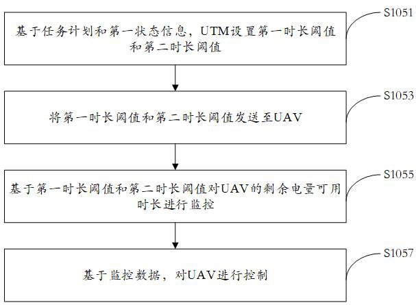
[0063] Step S105, based on the task plan and the first state information, the UTM sets a first monitoring strategy;

[0064] Step S107, when the state of the UAV satisfies the first trigger condition, adopt the first charging strategy;

[0065] Step S109 , based on the first charging strategy, select a corresponding charging cabinet to charge the UAV.

[0066] This embodiment can monitor the state of the UAV and perform corresponding control according to the monitoring results, can charge the UAV in t...

Embodiment 2

[0068] A charging method based on a UAV UAV charging cabinet proposed by the present invention includes the following steps:

[0069] In step S101, the UAV performs a self-check to obtain the first state information of the UAV, preferably, the first state information includes the battery power information of the UAV, the continuous working time information and the power consumption information of each component in the UAV;

[0070] Step S103, setting a mission plan, and sending the mission plan and the first state information to the UTM service management network element UTM;

[0071] Step S105, based on the task plan and the first state information, the UTM sets a first monitoring strategy;

[0072] Step S107, when the state of the UAV satisfies the first trigger condition, adopt the first charging strategy;

[0073] Step S109 , based on the first charging strategy, select a corresponding charging cabinet to charge the UAV.

[0074] This embodiment includes a monitoring str...

Embodiment 3

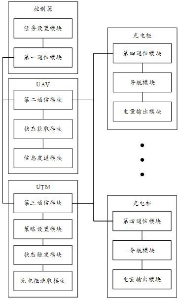
[0107] like Figure 4 As shown, the present invention also provides a charging system for a UAV charging cabinet, which may include a controller, a UAV, a UTM and a plurality of charging cabinets:

[0108] The controller includes a first communication module and a task setting module;

[0109] The communication module is configured to interface with UAV and UTM signals;

[0110] The mission setting module is configured to set the mission plan and send it to the UAV;

[0111] The UAV includes a second communication module, a state acquisition module and an information transmission module;

[0112] The second communication module is configured to be in signal connection with the controller, the UTM and the plurality of charging cabinets;

[0113] The state acquisition module is configured to perform self-check to acquire UAV first state information;

[0114] The information sending module is configured to send the mission plan and the first state information to the UTM;

[...


PUM


Abstract

The invention discloses a charging method and system based on a UAV charging cabinet, and the method comprises the steps: carrying out the self-inspection of a UAV, and obtaining the first state information of the UAV; setting a task plan, and sending the task plan and the first state information to an unmanned aerial vehicle system business management network element UTM; based on the task plan and the first state information, the UTM sets a first monitoring strategy; when the state of the UAV meets a first triggering condition, adopting a first charging strategy; and based on the first charging strategy, selecting a corresponding charging cabinet to charge the UAV. The unmanned aerial vehicle can be charged in time, the energy consumption of the unmanned aerial vehicle can be effectively controlled, the cruising ability of the unmanned aerial vehicle is improved, meanwhile, the power consumption of the unmanned aerial vehicle can be reduced by adopting targeted navigation of the charging cabinet in the later period, and the charging mode of the unmanned aerial vehicle is greatly facilitated.

Description

technical field [0001] The invention belongs to the field of computer system engineering, and in particular relates to a charging method and system based on a UAV charging cabinet of an unmanned aerial vehicle. Background technique [0002] UAV is an unmanned aerial vehicle controlled by radio remote control equipment or its own program control device. With the rapid development of the UAV industry, more and more UAVs are applied to industries such as agriculture, forestry, electric power, surveying and mapping, and telemetry. [0003] In various industrial applications, drones usually need to carry various equipment to achieve various functions. With the increase of equipment, the weight of the drone increases, and more power needs to be consumed to ensure the normal flight of the drone. Power consumption is large. However, drones are basically powered by batteries. The battery can provide limited power at one time, and the battery life is low. It is necessary to prepare ...

Claims


Application Information

Patent Timeline
IPC IPC(8): B60L53/67B60L53/68B60L53/62B60L53/66B60L53/35
CPCB60L53/67B60L53/68B60L53/62B60L53/665B60L53/35B60L2200/10B60L2240/54B60L2240/62B60L2240/66Y02T10/70Y02T10/7072
Inventor 戴永东曹世鹏张泽陈小勇蒋中军杨金明鞠玲丁安琪倪莎
Owner STATE GRID JIANGSU ELECTRIC POWER CO LTD TAIZHOU POWER SUPPLY BRANCH
Why Eureka
Try Eureka