
Sand-resistant gate valve

A gate valve and gate technology, which is applied to valve devices, valve details, sliding valves, etc., can solve the problems of sedimentation, limited vibration effect of knocking, and valves that cannot be completely closed.

Active Publication Date: 2022-07-22
SOUTHWEST PETROLEUM UNIV
View PDF9 Cites 0 Cited by
  • Summary
  • Abstract
  • Description
  • Claims
  • Application Information

AI Technical Summary

Problems solved by technology

As we all know, the actual fluid in production often contains particulate impurities. There are many sources of impurities, such as the sediment entrained in the fluid itself, such as the solid precipitation generated by the chemical reaction of the fluid, such as the rust generated by the corrosion of pipelines and equipment, etc. Some of them are more Small and lighter particles can easily flow with the fluid and will not affect the normal operation of the delivery system, but another part of larger and heavier particles will often settle down in the pipeline, and when the flow fluctuations of the delivery system disturb these When depositing, these particles tend to deposit again after a certain distance with the fluid flow, and the valve seat of the gate valve has become an ideal deposition point due to the concave area, which often leads to the valve not being able to be completely closed and the problem of lax closing
For the above problems, at present, the particles are usually separated from the valve body and taken away by the fluid by knocking the bottom of the valve body, but the way of knocking the valve body is not safe, especially for high-pressure valves, and for large valves or valve seats with concave For valves with deep grooves, the vibration effect of this kind of knocking is limited, and the particles will not leave the grooves, so the problem of loose closing cannot be solved.

Method used


Image

  • Sand-resistant gate valve
  • Sand-resistant gate valve
  • Sand-resistant gate valve

Examples


Embodiment 1

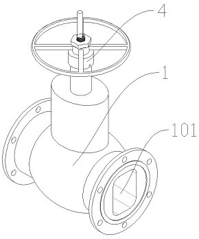
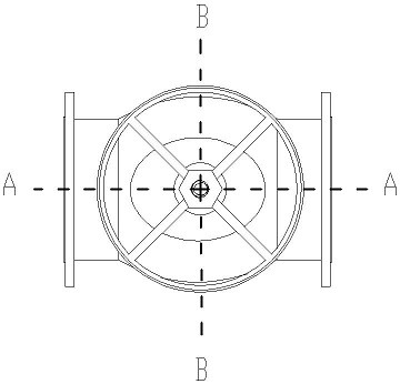
[0024] Please refer to Figure 2 to Figure 5 , figure 2 is a perspective view of the gate valve of this embodiment, image 3 Yes figure 2 top view, Figure 4 Yes image 3 Sectional view along section A-A, Figure 5 Yes image 3 Sectional view of section B-B.

[0025] The gate valve includes a valve body 1 , a gate 2 , a valve seat 3 and a driving structure 4 . The valve body 1 is provided with a fluid channel 101 that runs through the body as a channel for fluid flow; the valve seat 3 is located in the fluid channel 101 and is perpendicular to the fluid flow direction, and the driving structure 3 is used to drive the gate 2 to slide back and forth along the valve seat 3 so as to Open and close the fluid channel 101 .

[0026] The drive structure 4 includes a handwheel 401 and a valve stem 402. One end of the valve stem 402 is inserted into the valve body 1 and connected to the gate 2, and the valve stem 402 is sealedly connected to the valve body 1. The handwheel 401...

Embodiment 2

[0031] In order to further improve the flushing effect, part of the structure in Example 1 is improved in this implementation.

[0032]First of all, in order to reduce the gap between the bottom of the shutter 2 and the top of the first baffle 3012 when the shutter 2 is in the first position, a clearance fit is adopted between the shutter 2 and the first baffle 3012, and a clearance fit is adopted between the shutter 2 and the first baffle 3012. An elastic layer is provided on the upstream surface to seal the gap between the gate 2 and the first baffle 3012 .

[0033] Secondly, in order to prevent large particles from being intercepted, increase the minimum flow area of ​​the flow channel between the bottom of the gate 2 and the groove 3012. For details, refer to Figure 13 , the upper end of the first baffle 3012 is higher than the upper end of the second baffle 3013, and when the gate 2 is in the first position, the minimum flow area of ​​the flow passage between the bottom ...


PUM


Abstract

The invention discloses an anti-sand gate valve and belongs to the technical field of valve equipment, the gate valve comprises a valve body, a valve seat and a gate, the valve seat comprises a base and a fluid channel for opening and closing the valve body when the gate moves back and forth along the valve seat, a groove matched with the bottom of the gate is formed in the upper end face of the base, and baffles on the two sides of the groove are a first baffle and a second baffle respectively; the bottom of the back flow face of the flashboard is higher than the bottom of the incident flow face of the flashboard, and the flashboard has a first position in the downward moving process along the track, so that the bottom of the incident flow face of the flashboard is not higher than the upper end of the first baffle, and the flashboard does not block an outlet of the flushing runner. The bottom of the flashboard back-flow surface is higher than the upper end of the second baffle. In the valve closing process, the incident flow face of the gate plate is matched with the first baffle of the groove to reduce the flow area of fluid, the fluid is promoted to flow through the flushing runner to flush the groove, and the problem that the valve is not tightly closed due to particle deposition is avoided.

Description

technical field [0001] The invention relates to the technical field of valve equipment, in particular to an anti-sand gate valve. Background technique [0002] Gate valve is a common flow control device in fluid conveying system. It has functions such as cut-off and adjustment. It generally includes a valve body and a gate. The valve body is provided with a flow channel running through the body and a valve perpendicular to the direction of the flow channel. The gate is an opening and closing part. When in use, the gate slides along the valve seat to open and close the flow channel. It is well known that the actual fluid in production often contains particulate impurities, and the sources of impurities are various, such as the sediment entrained by the fluid itself, such as the solid precipitation generated by the chemical reaction of the fluid, such as the rust generated by the corrosion of pipes and equipment, etc. Small, lighter particles can easily flow with the fluid an...

Claims


Application Information

Patent Timeline
Patent Type & Authority Applications(China)
IPC IPC(8): F16K3/02F16K3/314F16K3/316F16K27/04
CPCF16K3/0281F16K3/314F16K3/316F16K27/044Y02E10/20
Inventor 周昱江李相红金琦杨崴韩文迪
Owner SOUTHWEST PETROLEUM UNIV
Learn More