


Quick Research
Generate reliable direction feasibility study reports for your R&D in just a few steps.

Technical Q&A
Discover and master advanced knowledge NOW. Basics, ideas, possibilities, all at once.

Find Solutions
As an expert in R&D theories, this can generate solutions to your technical problems instantly.

Evaluate Feasibility
Analyze your overall solution with one click, know your potential R&D risks in advance.

Monitor Landscape
Get weekly tech updates, stay abreast of the latest tech innovations and key insights.
Adjusting method and adjusting device for transmission shaft intermediate support
A technology of intermediate support and adjustment method, applied in the direction of control device, transportation and packaging, vehicle parts, etc., can solve the problem of poor control accuracy of equivalent angle adjustment, and achieve the effect of improving accuracy
- Summary
- Abstract
- Description
- Claims
- Application Information
AI Technical Summary
Problems solved by technology
Method used
Image


Examples
Embodiment 1
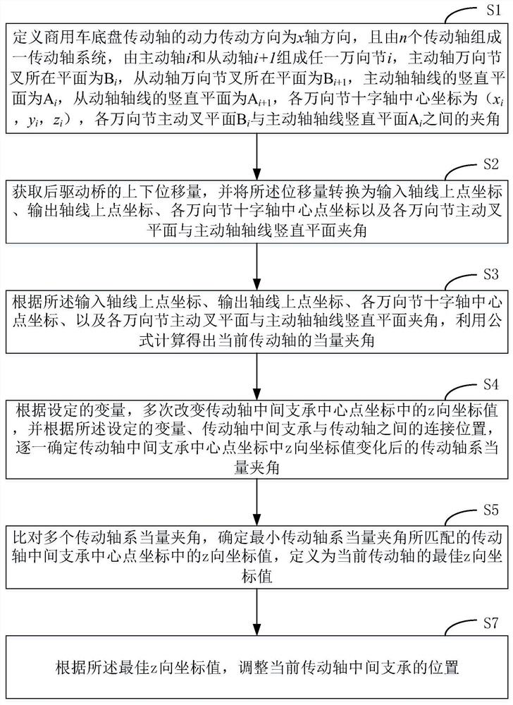
[0056] see figure 1 , figure 1 This is a schematic flowchart of an adjustment method for an intermediate support of a transmission shaft provided by an embodiment of the present application. Depend on figure 1 It can be seen that the adjustment method for the intermediate support of the transmission shaft in this embodiment mainly includes the following processes:
[0057] S1: Define the power transmission direction of the drive shaft of the commercial vehicle chassis as the x-axis direction, and a drive shaft system is composed of n drive shafts. Any universal joint is formed by the driving shaft and the corresponding driven shaft. The driving shaft is universal The plane where the yoke is located is B i , the plane of the driven shaft universal joint fork is B i+1 , the vertical plane of the drive shaft axis is A i , the vertical plane of the driven shaft axis is A i+1 , the center coordinate of each universal joint cross axis is (x i , y i ,z i ), each universal jo...
Embodiment 2
[0077] exist figure 1 and figure 2 On the basis of the embodiment shown, see image 3 , image 3 This is a schematic structural diagram of an adjusting device for intermediate support of a transmission shaft provided in an embodiment of the present application. Depend on image 3 It can be known that the adjusting device used for the intermediate support of the transmission shaft in this embodiment mainly includes a hydraulic lifting module, a displacement sensor and a control module. The adjusting device in this embodiment is applied to the drive shaft of a commercial vehicle chassis.
[0078] Among them, the displacement sensor is used to measure the up and down displacement of the rear drive axle, and convert the displacement into the coordinates of the points on the input axis, the coordinates of the points on the output axis, the coordinates of the center point of the cross shafts of each universal joint, and the plane of the active fork of each universal joint. The...
PUM
 Abstract
Description
Claims
Application Information
 - R&D Engineer
- R&D Manager
- IP Professional
- Industry Leading Data Capabilities
- Powerful AI technology
- Patent DNA Extraction
Browse by: Latest US Patents, China's latest patents, Technical Efficacy Thesaurus, Application Domain, Technology Topic, Popular Technical Reports.
© 2024 PatSnap. All rights reserved.Legal|Privacy policy|Modern Slavery Act Transparency Statement|Sitemap|About US| Contact US: help@patsnap.com