Workpiece positioning mechanism of laser cutting machine

A laser cutting machine and positioning mechanism technology, applied in laser welding equipment, manufacturing tools, metal processing equipment, etc., can solve the problems of workpiece deformation, cutting size error, unstable fixation, etc., to improve quality, improve stability, reduce effect of contact

Active Publication Date: 2022-07-22
扬州屹丰汽车部件有限公司
View PDF13 Cites 0 Cited by
  • Summary
  • Abstract
  • Description
  • Claims
  • Application Information

AI Technical Summary

Problems solved by technology

[0003] Among them, the laser cutting machine has the fastest efficiency, the highest cutting precision, and the cutting thickness is generally small. However, when the existing laser cutting machine cuts the workpiece, the workpiece often The fixation is not stable, resulting in errors in the cutting size, which in turn affects the quality of the cut workpiece; at the same time, in order to prevent the high temperature generated during the cutting process from sticking the workpiece and the platform together, most of the existing workpiece positioning mechanisms for laser cutting use two sets of The clamping mechanism clamps and fixes both ends of the workpiece and lifts it up for cutting. During the laser cutting process, due to the lack of corresponding auxiliary support structures, the laser cutting part falls under gravity, resulting in deformation of the workpiece and affecting the quality of the cut workpiece.

Method used


Image

  • Workpiece positioning mechanism of laser cutting machine
  • Workpiece positioning mechanism of laser cutting machine
  • Workpiece positioning mechanism of laser cutting machine

Examples


specific Embodiment 1

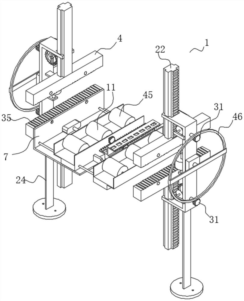
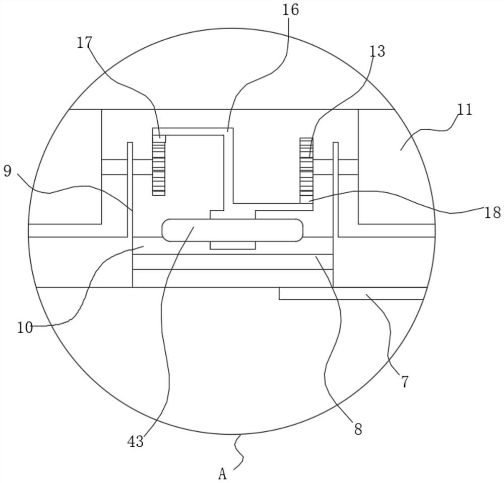
[0037] see Figure 1-11 As shown, the present invention is a workpiece positioning mechanism of a laser cutting machine, comprising two sets of clamping assemblies 1 arranged oppositely; the two clamping assemblies 1 clamp the workpiece 2; the clamping assembly 1 includes a clamping frame 3; The frame 3 is symmetrically slidably fitted with a clamping plate 4; the clamping plate 4 at the bottom is fixedly connected with a mounting frame 5 by fastening bolts; the installation frame 5 is slidably fitted with a transmission assembly 6; A sliding rod 8 is symmetrically and fixedly connected to the side of the fixing plate 7; the transmission assembly 6 includes two parallel mounting platforms 9; a mounting plate 10 is symmetrically and fixedly connected between the two mounting platforms 9; Mounting holes 12 are symmetrically opened on the side of the table 9; the mounting holes 12 are slidingly matched with the sliding rod 8; one end of the rotating shaft of the driving roller 11...

specific Embodiment 2

[0039] On the basis of the specific embodiment 1, the differences of this embodiment are:

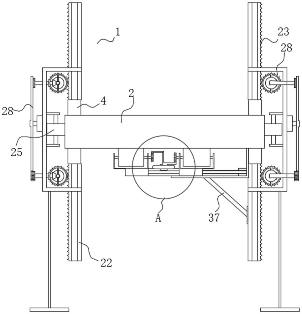
[0040] like figure 1 , 5 -7 and Figure 11 As shown, the clamping frame 3 includes a C-shaped plate 19; the two ends of the C-shaped plate 19 are symmetrically opened with limit channels 20; the two sides of the limit channel 20 are symmetrically opened with guide channels 21; The slide plate 22; the slide plate 22 is slidingly matched with the guide channel 21; the side surface of the slide plate 22 is fixedly connected with a gear plate 23; the gear plate 23 is slidingly matched with the limit channel 20; The side of the 19 is rotatably matched with the drive roller 25; the side of the C-shaped plate 19 is located on both sides of the drive roller 25 and is fixedly connected to the connecting plate 26; the side of the connecting plate 26 is fixedly connected with a first rotating shaft 27; ; The gear ring 28 meshes with the gear plate 23 .

[0041] A first conical tooth 29 is fixe...

specific Embodiment 3

[0043] On the basis of the second specific embodiment, the difference of this embodiment lies in:

[0044] like Figure 7-8 As shown, the other side of the clamping plate 4 is provided with anti-skid lines 35; the adjacent sides of the clamping plate 4 are symmetrically provided with first threaded holes 36; the C-shaped plate 19 is fixed on the clamping plate 4 by fastening bolts; A diagonal brace 37 is fixedly connected to the bottom surface of the plate 19;

[0045] A specific application of this embodiment is as follows: the opening of the anti-skid grooves 35 increases the friction between the workpiece 2 and the clamping plate 4 and improves the clamping stability of the clamping plate 4; stability.


PUM


Abstract

The invention discloses a workpiece positioning mechanism of a laser cutting machine, and relates to the technical field of laser processing. The clamping device comprises two sets of clamping assemblies which are oppositely arranged. The clamping frame is symmetrically matched with clamping plates in a sliding manner; the mounting frame is in sliding fit with a transmission assembly; the mounting hole is in sliding fit with the sliding rod; a rotating shaft at one end of the driving roller penetrates through the mounting table and is fixedly connected with a rotating gear; the two sliding channels are in sliding fit with sliding pieces. And the upper gear rack and the lower gear rack are respectively meshed and matched with the two rotating gears. A workpiece is clamped and fixed through the clamping plates on the two clamping frames, and the servo motor is started to drive the lead screw to rotate, so that the transmission assembly is driven to slide, the to-be-cut position is located between the two mounting tables, and the workpiece is positioned and supported; and after cutting is completed, clamping and fixing of the clamping plate are relieved, the sliding piece is pulled, the two rotating gears are driven to synchronously and reversely rotate, and therefore the two sets of driving rollers are driven to synchronously and reversely rotate, and the cut workpieces are synchronously and reversely conveyed out of the corresponding mounting tables.

Description

technical field [0001] The invention belongs to the technical field of laser processing equipment, in particular to a workpiece positioning mechanism of a laser cutting machine. Background technique [0002] With the development of modern mechanical processing industry, the requirements for cutting quality and precision are constantly improving, and the requirements for improving production efficiency, reducing production costs, and having highly intelligent automatic cutting functions are also increasing. The development of CNC cutting machine must meet the requirements of the development of modern mechanical processing industry. Cutting machines are divided into flame cutting machines, plasma cutting machines, laser cutting machines, water cutting machines, etc. [0003] Among them, the laser cutting machine has the fastest efficiency, the highest cutting accuracy, and the cutting thickness is generally small. However, when the existing laser cutting machine cuts the work...

Claims


Application Information

Patent Timeline
IPC IPC(8): B23K26/70B23K26/38
CPCB23K26/70B23K26/38
Inventor 岳云锋孔伟伟刘家雨郭颂
Owner 扬州屹丰汽车部件有限公司
Why Eureka
Try Eureka