
Control system rod force gradient modeling method based on system identification

A technology for manipulating systems and system identification, applied in instrumentation, geometric CAD, design optimization/simulation, etc., can solve the problems of poor model robustness, difficult model adjustment, and high cost of adding sensors, and achieve model simplification, efficiency improvement and Stability, the effect of a small amount of measurement data

Pending Publication Date: 2022-07-15
BEIHANG UNIV
View PDF0 Cites 0 Cited by
  • Summary
  • Abstract
  • Description
  • Claims
  • Application Information

AI Technical Summary

Problems solved by technology

However, the cost of adding sensors is too expensive, and some parameters are difficult to measure by simply adding sensors
In addition, in order to calibrate the design parameters, the control system is required to be able to move the full range under different flight conditions, which is impossible to achieve during the flight
[0009] Modeling based on the design principles of the control system often leads to complex modeling of the control system model. When the control system changes, it is difficult to adjust the model and the model is less robust

Method used


Image

  • Control system rod force gradient modeling method based on system identification
  • Control system rod force gradient modeling method based on system identification
  • Control system rod force gradient modeling method based on system identification

Examples


Embodiment Construction

[0025] The present invention will be further described in detail below in conjunction with the accompanying drawings.

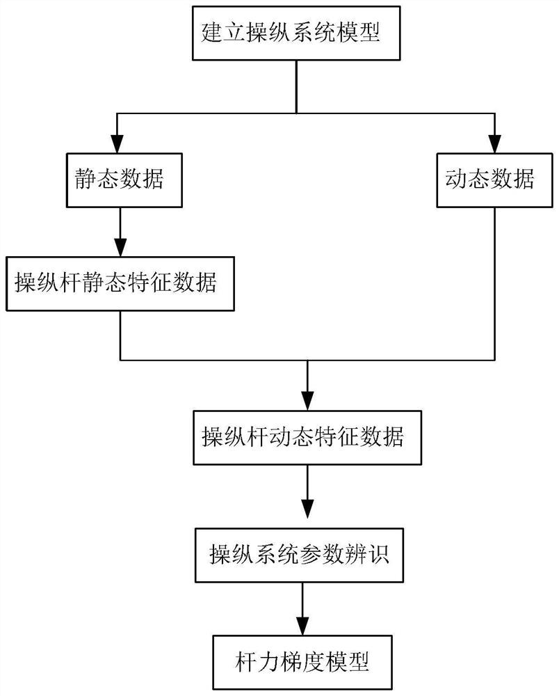
[0026] The present invention is based on the system identification-based modeling method of the lever force gradient of the control system, such as figure 1 shown, including the following steps:

[0027] Step 1: Determine the preliminary model structure of the flight control system.

[0028] At present, there are several flight control systems such as mechanical control, hydraulic power control, and fly-by-wire control. For different types of control systems, there are certain differences in the influencing factors of the stick force gradient.

[0029] The following takes the hydraulic power steering system as an example to illustrate:

[0030] The rod force gradient of the hydraulic power steering system is generally affected by the centering spring, friction force, the feeling force of the human sensor system, and the motion damping.

[0031] The centeri...


PUM


Abstract

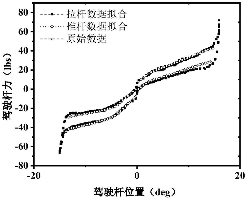
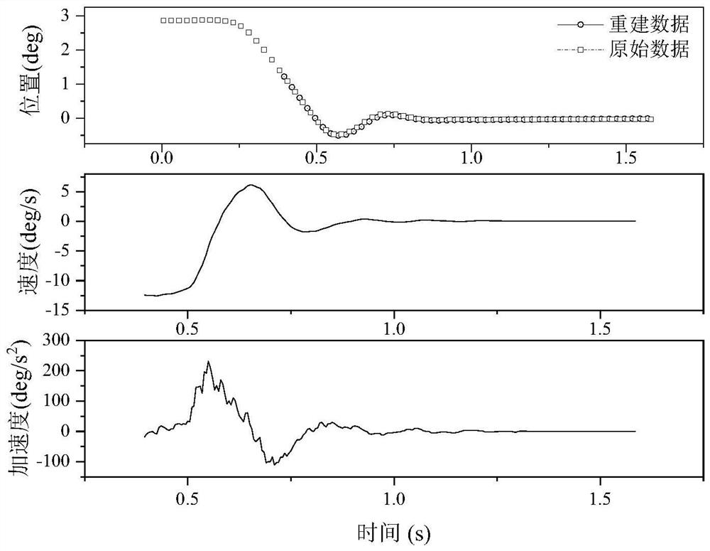
The invention discloses a control system rod force gradient modeling method based on system identification. The control system rod force gradient modeling method has huge advantages and potential for modeling and simulating a control load system in a flight simulator. The method comprises the following steps: firstly, preliminarily assuming a control system model according to the type of an aircraft control system to obtain a control system model equation and parameters required by modeling; performing extraction and modeling on static force characteristics of the control system by utilizing a'rod force-displacement 'test of the control system; a dynamic characteristic curve in the joystick release process is obtained through different joystick release tests in the take-off stage, the cruise stage and the landing stage; and carrying out system identification by taking the static characteristic curve as a reference and utilizing the dynamic characteristic curve to obtain each unknown parameter in the established control system model so as to obtain a complete control system simulation model.

Description

technical field [0001] The invention belongs to the technical field of aircraft control system design and flight simulation, and in particular relates to a system identification-based method for modeling the lever force gradient of a control system. Background technique [0002] The control load system is one of the important components of high-level flight simulators, which can provide pilots with real joystick force feedback during simulation training. Authenticity will directly affect the pilot's aircraft control memory. In the objective identification standards for training simulators at all levels, in order to ensure the effectiveness of simulation training, subjects are set up to test the authenticity of the control load system model, mainly including: "Stick Force-Displacement" test and "Joystick Release" test. [0003] When performing a "stick force-displacement" test, the tester needs to move the stick slowly over the full stroke of the stick to obtain a "stick for...

Claims


Application Information

Patent Timeline
Patent Type & Authority Applications(China)
IPC IPC(8): G06F30/15G06F30/20G06F119/14
CPCG06F30/15G06F30/20G06F2119/14
Inventor 蔡向群李卫琪戴树岭赵永嘉雷小永
Owner BEIHANG UNIV
Learn More