
Spatial Error Prediction Method of Three-axis CNC Machine Tool Based on Feature Points of Error Field

A CNC machine tool and space error technology, applied in the field of CNC, can solve the problems of large amount of interpolation calculation, communication lag, and large system burden, and achieve the effect of less measurement data, high real-time compensation, and small amount of calculation

Active Publication Date: 2022-04-01
XY HUST ADVANCED MFG ENG RES INST
View PDF9 Cites 0 Cited by
  • Summary
  • Abstract
  • Description
  • Claims
  • Application Information

AI Technical Summary

Problems solved by technology

The patent "A Method for Measuring the Space Error of the Full Stroke of a Machine Tool" proposes a method for directly measuring the error of the full working space of the machine tool. However, the installation of the measuring instrument has very strict requirements on light, and at the same time, it is limited by the structure of the machine tool. These reasons greatly limit its Application and promotion; At the same time, through literature search, it was found that there are a large number of literatures that use the homogeneous coordinate transformation to directly calculate the three-axis error data of the CNC machine tool, thereby obtaining the error of any position in the machine tool space. The amount of interpolation calculations in the process is too large, which leads to an excessive burden on the system, and it is difficult to apply it to the CNC system for real-time compensation. Therefore, the patent "Real-time Compensator for CNC Machine Tool Errors Based on the Offset of the External Coordinate Origin of the Machine Tool (CN105700472A)" proposes to use plug-in The compensator independently calculates the compensation value of the machine tool space error through the compensator calculation module, and sends it to the CNC system for real-time compensation. However, due to problems such as interface with the CNC system and communication lag, it is still difficult to be applied in practice.

Method used


Image

  • Spatial Error Prediction Method of Three-axis CNC Machine Tool Based on Feature Points of Error Field
  • Spatial Error Prediction Method of Three-axis CNC Machine Tool Based on Feature Points of Error Field
  • Spatial Error Prediction Method of Three-axis CNC Machine Tool Based on Feature Points of Error Field

Examples


Embodiment Construction

[0017] In order to make the purpose, technical solutions and advantages of the embodiments of the present invention clearer, the technical solutions in the embodiments of the present invention will be clearly and completely described below in conjunction with the drawings in the embodiments of the present invention. Obviously, the described embodiments It is a part of embodiments of the present invention, but not all embodiments. The components of the embodiments of the invention generally described and illustrated in the figures herein may be arranged and designed in a variety of different configurations.

[0018] Accordingly, the following detailed description of the embodiments of the invention provided in the accompanying drawings is not intended to limit the scope of the claimed invention, but merely represents selected embodiments of the invention. Based on the embodiments of the present invention, all other embodiments obtained by persons of ordinary skill in the art wi...


PUM


Abstract

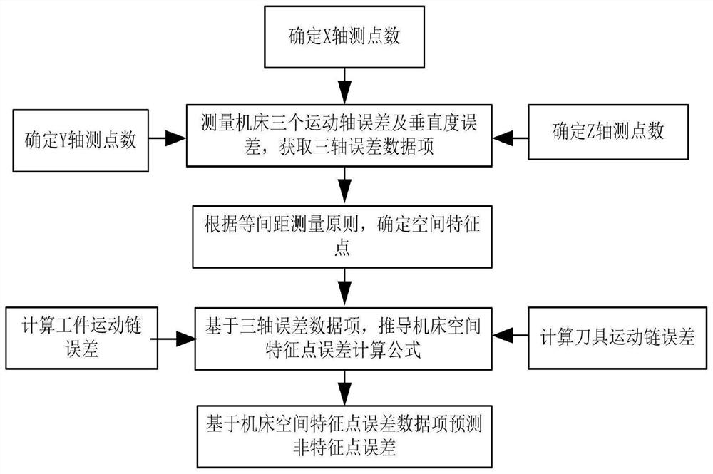
The invention discloses a spatial error prediction method of a numerical control machine tool based on error field feature points, comprising the steps of: a. measuring the errors of the three motion axes and the verticality error of the machine tool, and obtaining three-axis error data items; b. according to the three-axis error data Calculate the three-term error of the feature point space of the error field of the machine tool and store it in the numerical control system; c. Predict the error compensation value of the non-feature point error in the machine tool space according to the feature point error data of the 8 vertices of the cube. It measures the error data of the three motion axes of the machine tool and the verticality error data, calculates the three-item error of the feature points of the machine tool space according to the three-axis error data, and then predicts the non-linear position in the cube based on the error data of the eight vertex feature points of the cube. The error of any position of the feature point. This method will have the advantages of less measurement data, less computation, high real-time compensation, and reliable accuracy.

Description

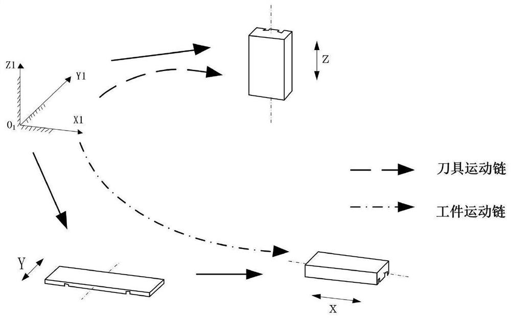
technical field [0001] The invention relates to the technical field of numerical control, in particular to a spatial error prediction method of a three-axis numerical control machine tool based on error field feature points. Background technique [0002] A three-axis CNC machine tool includes three linear motion axes, and the machine tool produces errors due to manufacturing and assembly. The rigid body has 6 degrees of freedom in space, so each linear motion axis has 6 error elements in space, that is, 3 movement errors and 3 angle errors, a total of 18 errors in the three axes, plus two and two of the three axes 3 items of squareness errors caused by not being perfectly vertical, so a total of 21 items of errors. At present, the relatively mature error compensation method adopts the single-axis error compensation method, that is, the error items of the three motion axes of the machine tool are respectively compensated, including the verticality error compensation, but bec...

Claims


Application Information

Patent Timeline
Patent Type & Authority Patents(China)
IPC IPC(8): G05B19/401G05B19/404
CPCG05B19/404G05B19/401G05B2219/45013
Inventor 陈国华胡海莹向华张林王超李波赵殿章
Owner XY HUST ADVANCED MFG ENG RES INST
Learn More