Optical fiber carbon quantum dot pressure detection system
A technology of carbon quantum dots and detection systems, which can be used in the measurement of fluid pressure, the measurement of fluid pressure using optical methods, and the measurement of the change in optical properties of materials when they are stressed, which can solve the inconvenience of application and affect the output. Light detection and other issues, to achieve good application prospects, low detector requirements, simple data processing effect
- Summary
- Abstract
- Description
- Claims
- Application Information
AI Technical Summary
Problems solved by technology
Method used
Image

Examples
Embodiment 1
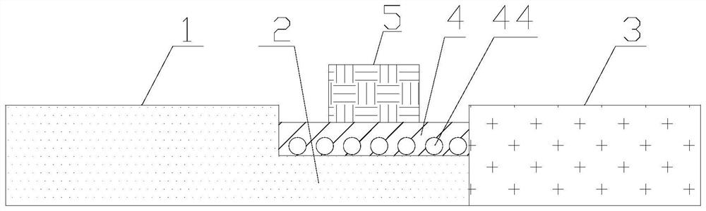
[0023] The present invention provides an optical fiber carbon quantum dot pressure detection system, including a light source, a light detector, a first optical fiber 1 , a connecting part 2 , a second optical fiber 3 , a composite sensing material 4 , and a force receiving part 5 . One end of the first optical fiber 1 is connected to the light source. The light source is an ultraviolet light source, the light source emits ultraviolet light, and the ultraviolet light is coupled into the first optical fiber 1 . The first optical fiber 1 is an ultraviolet optical fiber, so that the ultraviolet light can propagate in the first optical fiber 1 and generate less loss. like figure 1 As shown, the other end of the first optical fiber 1 is connected to one end of the connecting part 2, the other end of the connecting part 2 is connected to one end of the second optical fiber 3, and the other end of the second optical fiber 3 is connected to the photodetector. The light detector incl...
Embodiment 2
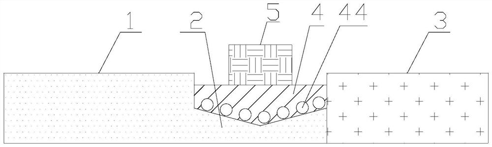
[0032] On the basis of Example 1, as figure 2 As shown, the connecting portion 2 is V-shaped, the middle of the connecting portion 2 is low, the two sides of the connecting portion 2 are high, and the force-receiving portion 5 is placed on the upper side of the V-shape. In this way, more carbon quantum dots 44 can be arranged in the V-shaped groove, and these carbon quantum dots 44 generate stronger fluorescence. In particular, when pressure is applied on the force receiving portion 5, since the carbon quantum dots 44 move to the lower side of the V-shaped groove, the distance between the carbon quantum dots 44 changes more, thereby changing the center of the fluorescence emission more. wavelength, enabling more sensitive pressure detection. The force-receiving part 5 is arranged on the upper side of the V-shaped groove, and the area of the force-receiving part 5 is larger than the top area of the V-shaped groove, and the force-receiving part 5 confines the fluorescence ...
Embodiment 3
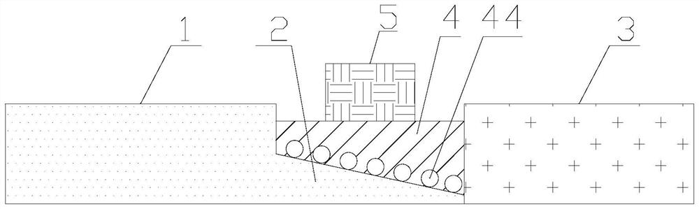
[0036] On the basis of Example 1, as image 3 As shown, the end of the connecting portion 2 connected with the first optical fiber 1 is high, and the end of the connecting portion connected with the second optical fiber 3 is low. That is, the cross-sectional area of one end of the connecting portion 2 in contact with the first optical fiber 1 is large; the cross-sectional area of the one end of the composite sensing material 4 in contact with the second optical fiber 3 is large. Such a design facilitates the propagation of more ultraviolet light to the connecting portion 2 , thereby exciting the carbon quantum dots 44 to generate stronger fluorescence, and also facilitates more coupling of the fluorescence generated by the carbon quantum dots 44 into the second optical fiber 3 .
[0037] Further, the bottom surface of the force receiving portion 5 is provided with a precious metal layer, the material of the precious metal is gold, and the thickness of the precious metal la...
PUM
| Property | Measurement | Unit |
|---|---|---|
| thickness | aaaaa | aaaaa |
Abstract
Description
Claims
Application Information
 - R&D
- Intellectual Property
- Life Sciences
- Materials
- Tech Scout
- Unparalleled Data Quality
- Higher Quality Content
- 60% Fewer Hallucinations
Browse by: Latest US Patents, China's latest patents, Technical Efficacy Thesaurus, Application Domain, Technology Topic, Popular Technical Reports.
© 2025 PatSnap. All rights reserved.Legal|Privacy policy|Modern Slavery Act Transparency Statement|Sitemap|About US| Contact US: help@patsnap.com