Split plug-in type surface acoustic wave temperature sensor
A temperature sensor, surface acoustic wave technology, applied in thermometers, thermometers with physical/chemical changes, instruments, etc., can solve the problems of switch cabinet discharge, lower antenna height, sensor damage, etc., to achieve reasonable installation methods and tight fit , the effect of reducing the overall volume
- Summary
- Abstract
- Description
- Claims
- Application Information
AI Technical Summary
Problems solved by technology
Method used
Image
Examples
Embodiment 1
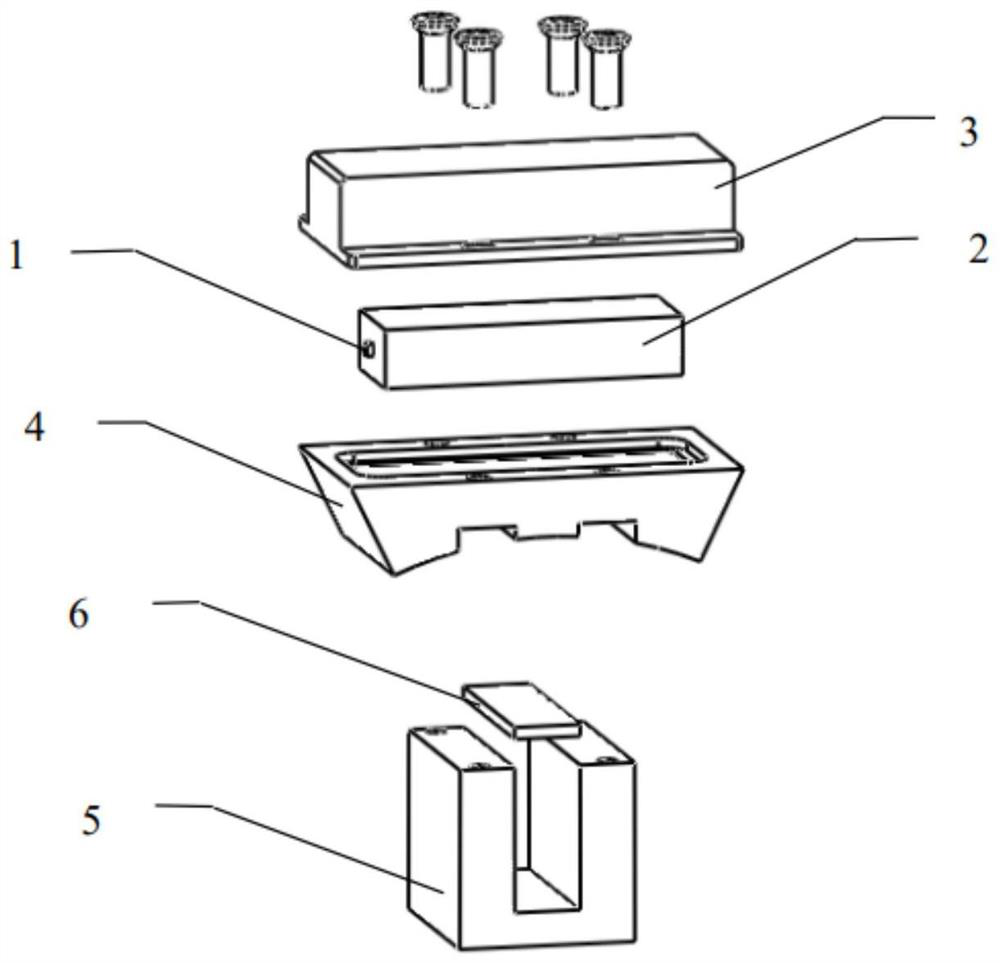
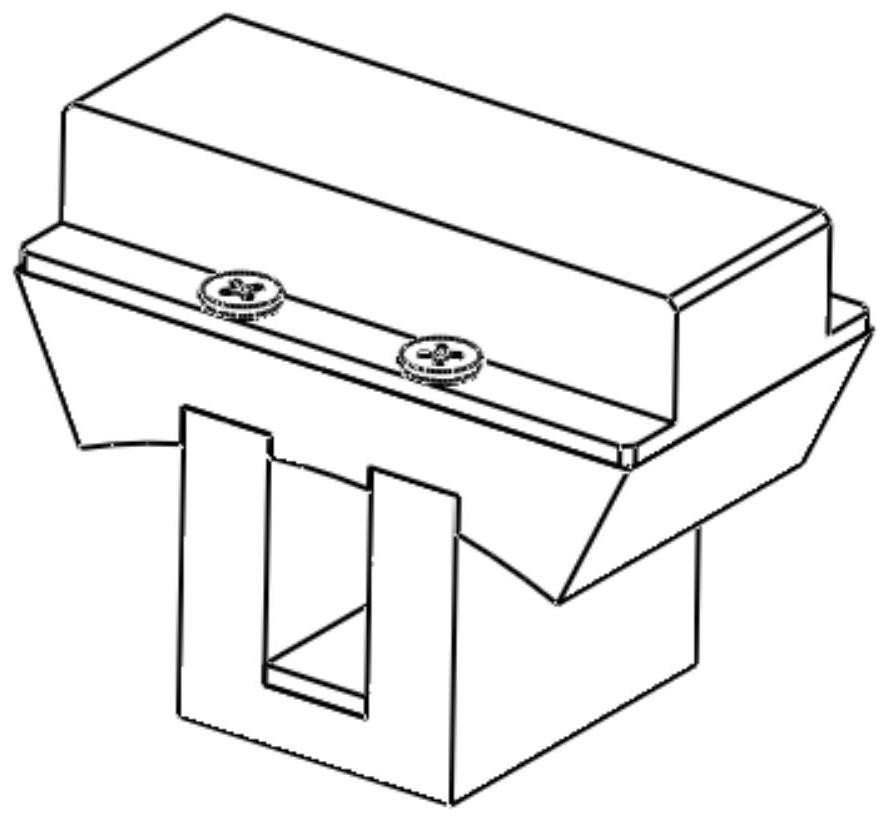
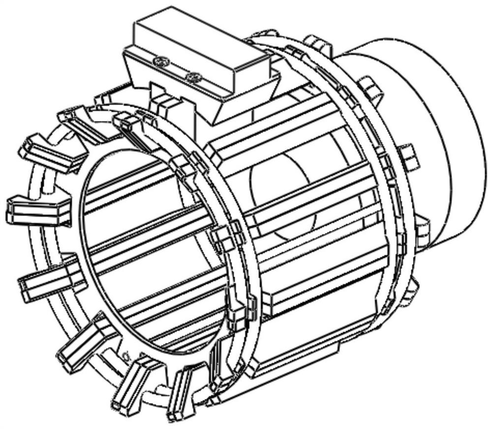
[0047] like figure 1 As shown in the figure, a separate plug-in type surface acoustic wave temperature sensor includes a surface acoustic wave temperature sensing chip 1, a ceramic antenna 2, a sensor shell 3, an arc-shaped upper bracket 4, a groove-type lower bracket 5, and a thermally conductive gasket 6. ; SAW temperature sensing chip 1, fixedly connected to the side of ceramic antenna 2; Ceramic antenna 2, arranged in sensor housing 3; Sensor housing 3, the interior space matches with ceramic antenna 2; Sensor housing 3 and ceramic antenna 2 are The arc-shaped upper bracket 4 is connected with screws and sealed with insulating glue; The thermal conductive gasket 6 is placed at the bottom of the groove-type lower bracket 5; the thermal conductive gasket 6 has an appropriate thickness; ensure that the arc-shaped upper bracket 4 and the groove-type lower bracket are in close contact with the metal part of the chrysanthemum head after installation. The arc-shaped upper bracke...
Embodiment 2
[0064] like Figure 8 As shown in the figure, a separate plug-in type surface acoustic wave temperature sensor includes a surface acoustic wave temperature sensing chip 1, a ceramic antenna 2, a sensor shell 3, an arc-shaped upper bracket 4, a groove-type lower bracket 5, and a thermally conductive gasket 6. , conductive film 7; surface acoustic wave temperature sensing chip 1, fixedly connected to the side of the ceramic antenna 2; ceramic antenna 2, arranged in the sensor housing 3; sensor housing 3, the internal space and ceramic antenna 2 match; ceramic antenna 2 and arc The conductive film 7 is filled between the upper brackets 4, and the outer cover reinforcement 3-2 on the top of the sensor shell 3 is pressed on the antenna radiating surface 2-1 of the ceramic antenna 2, and the ceramic antenna 2 is pressed by the elasticity of the conductive film 7. The top end face of the arc upper bracket 4 . The sensor shell is connected with the arc-shaped upper bracket 4 by screw...
PUM
| Property | Measurement | Unit |
|---|---|---|
| height | aaaaa | aaaaa |
Abstract
Description
Claims
Application Information
 - R&D Engineer
- R&D Manager
- IP Professional
- Industry Leading Data Capabilities
- Powerful AI technology
- Patent DNA Extraction
Browse by: Latest US Patents, China's latest patents, Technical Efficacy Thesaurus, Application Domain, Technology Topic, Popular Technical Reports.
© 2024 PatSnap. All rights reserved.Legal|Privacy policy|Modern Slavery Act Transparency Statement|Sitemap|About US| Contact US: help@patsnap.com


