
Drill jumbo and drill boom system

A technology for drilling booms and booms, which is applied in the field of rock drilling rigs and drilling boom systems. It can solve the problems of increasing the weight of the boom end, inconvenient operation of the boom system, and bulky boom system, and achieves output torque and braking torque. The effect of low size requirements, weight reduction, and increased flexibility

Pending Publication Date: 2022-07-15
CHINA RAILWAY CONSTR HEAVY IND
View PDF0 Cites 0 Cited by
  • Summary
  • Abstract
  • Description
  • Claims
  • Application Information

AI Technical Summary

Problems solved by technology

When the whole vehicle is driving in the tunnel, due to the large turning radius, it is necessary to ensure a large enough driving space, resulting in inconvenient driving
Secondly, the operating height and range of the telescopic boom are contradictory. When the pitch angle of the boom becomes larger, it is difficult to meet the requirements of the operating range while ensuring that the operating height meets the construction requirements; A compensation cylinder with a large stroke is set in the lower part, resulting in a swing cylinder or reducer that requires a larger torque and holding moment, which increases the weight of the end of the boom, and the whole boom system is quite bulky
[0003] Therefore, how to solve the problem of inconvenient operation of the boom system has become a technical problem to be solved by those skilled in the art

Method used


Image

  • Drill jumbo and drill boom system
  • Drill jumbo and drill boom system
  • Drill jumbo and drill boom system

Examples


Embodiment 1

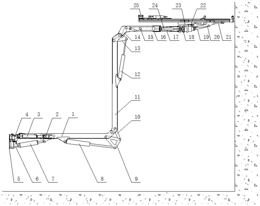
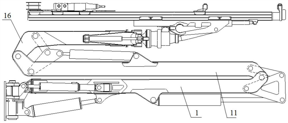
[0038] In this embodiment, the telescopic boom adopts a three-stage boom body as an example to illustrate the folding and unfolding method. refer to Figure 1 to Figure 3 , the drill boom system includes a connecting seat 5, a first boom 1, a second boom 11 and a third boom 16, the first boom 1, the second boom 11 and the third boom 16 are closed in a "Z" fold. The drive link mechanism includes a first link 9, a second link 10, a third link 13, a fourth link 14, a first deployment cylinder 8 and a second deployment cylinder 12; the first link 9, the second link The rod 10 and the first deployment cylinder 8 are used to drive the second boom 11 to fold and unfold relative to the first boom 1, and the third link 13, the fourth link 14 and the second deployment cylinder 12 are used to drive the third arm The frame 16 is folded and unfolded relative to the second boom frame 11 , and the telescopic boom frame is connected to the third boom frame 16 .

[0039]Specifically, the fi...

Embodiment 2

[0045] refer to Figure 4 and Figure 5 , in the drill boom system provided in this embodiment, the folding boom still adopts the form of the first boom 1, the second boom 11 and the second boom 11 being hinged in sequence, and the driving link mechanism includes the first link 9, The second link 10, the third link 13, the fourth link 14, the first deployment cylinder 8 and the second deployment cylinder 12; the first link 9, the second link 10 and the first deployment cylinder 8 are used to drive The second boom 11 is folded and unfolded relative to the first boom 1 . The third link 13 , the fourth link 14 and the second deployment cylinder 12 are used to drive the third boom 16 to fold and unfold relative to the second boom 11 . , the telescopic boom is connected to the third boom 16 . The first link 9 and the third link 13 are both triangular links. The difference is that the first link 9 is hinged to the second boom 11, the second link 10 is hinged to the first boom 1, a...

Embodiment 3

[0047] refer to Image 6 In this embodiment, on the basis of Embodiment 1, the positions of the third link 13, the fourth link 14 and the second deployment cylinder 12 that drive the folding and unfolding of the second boom 11 and the third boom 16 are adjusted, After the folding boom is folded, the second unfolding cylinder 12 is located below the second boom 11 .


PUM


Abstract

The invention discloses a drill jumbo and a drill boom system.The drill boom system comprises a telescopic boom frame and a folding boom frame, and the folding boom frame comprises at least two hinged boom frame bodies and a driving connecting rod mechanism for driving the adjacent boom frame bodies to be folded / unfolded; and the telescopic arm frame is connected with the arm frame body of the last stage of the folding arm frame. According to the drill boom system, the unfolding and folding time of the boom system can be shortened, and operation is convenient; the space of the folded boom is reduced, the turning radius is smaller, and the turnover is flexible; and the compensation operation amplitude of the telescopic boom is reduced, so that the tail end of the telescopic boom is obviously lightened.

Description

technical field [0001] The present application relates to the technical field of construction machinery, in particular to a rock drilling rig and a drill boom system. Background technique [0002] The rock drilling rig is also called drilling rig, which is an important equipment in the construction of tunnel drilling and blasting method. The telescopic structure is generally a single-cylinder first-level telescopic boom. This structure has the following problems: First, in order to meet the working height and range of the boom, the boom is generally long. During the driving process of the whole vehicle in the tunnel, due to the large turning radius, it is necessary to ensure a large enough driving space, which makes driving inconvenient. Secondly, the working height and range of the telescopic boom are contradictory. When the pitch angle of the boom becomes larger, it is difficult to ensure the working height meets the construction requirements and at the same time it is di...

Claims


Application Information

Patent Timeline
Patent Type & Authority Applications(China)
IPC IPC(8): E21B15/00E21B19/086E21B7/02E21D20/00
CPCE21B15/003E21B19/086E21B7/023E21B7/022E21D20/003
Inventor 刘飞香廖金军张裕生刘金书潘国智张贤福丁羽锋周昊朱坤杰
Owner CHINA RAILWAY CONSTR HEAVY IND
Learn More