
Patsnap Eureka
For R&D, Patsnap Eureka makes reading and utilizing patents & technical documents easy.
Patsnap Eureka AIR
Designed for self-driven R&D workflows. Generate viable solutions, solve complex R&D challenges, empower your innovation with AI.

Patsnap Eureka Materials
Designed for material experts only. Revolutionize your material R&D, from search, analyze, to developing new materials.

TechResearch
Generate reliable direction feasibility study reports for your R&D in just a few steps.

TechSeek
Discover and master advanced knowledge NOW. Basics, ideas, possibilities, all at once.

TechMind
As an expert in R&D Theories, TechMind can generates customized viable solutions instantly.

TechRisk
Analyze your overall solution with one click, know your potential R&D risks in advance.

TechMonitor
Get weekly tech updates, stay abreast of the latest tech innovations and key insights.
Protection structure for preventing garbage from being sucked into cleaning equipment due to neglected loading of filter element
A technology for cleaning equipment and protecting structures, applied in cleaning equipment, cleaning methods and utensils, and cleaning methods using gas flow, etc., can solve problems such as difficult cleaning and pollution, and achieve the effect of user friendliness and cost saving of electronic testing.
- Summary
- Abstract
- Description
- Claims
- Application Information
AI Technical Summary
Problems solved by technology
Method used
Image

Examples
Embodiment 1
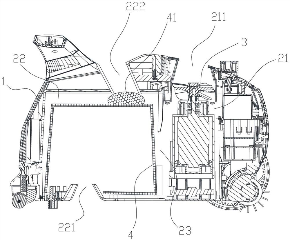
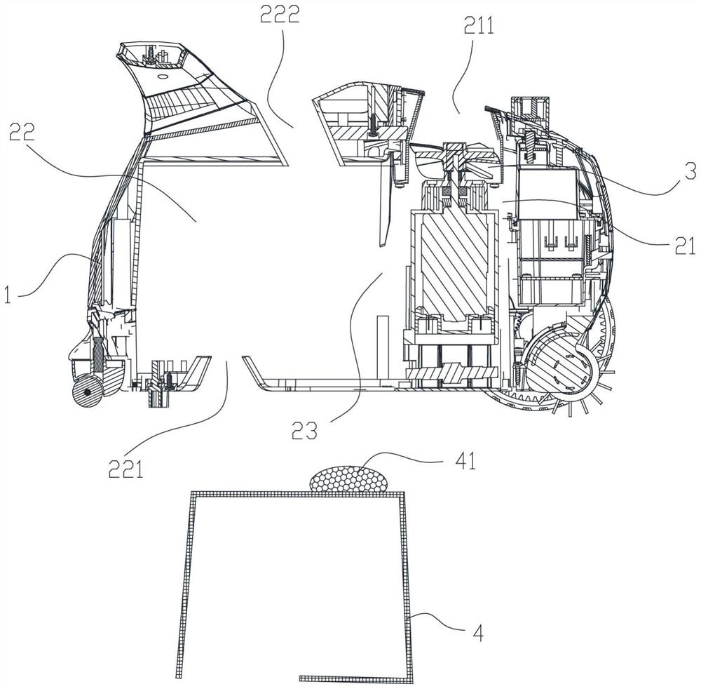
[0048] Example one, as figure 1 , 2 and Figure 4 shown:
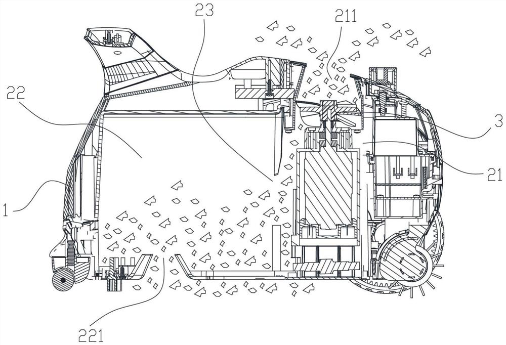
[0049] The protective structure for preventing garbage from being sucked into the cleaning equipment due to missing filter elements includes a casing 1. The casing 1 is provided with a first cavity 21 for accommodating the impeller 3, and a second cavity 22 for accommodating the filter element 4. The first cavity 21 is connected with the discharge port 211, the second cavity 22 is connected with the sewage suction port 221, the first cavity 21 and the second cavity 22 are connected through the first channel 23, and there is also a connection between the second cavity 22 and the outside world. The number of the second channel 222 is more than one, and the filter element 4 is provided with a blocking member 41 for blocking the second channel 222.
[0050] The cleaning robot with the impeller 3 is the negative pressure generated in the first cavity 21 by the rotation of the impeller 3, so that the external fluid is pre...
Embodiment 2
[0053] Embodiment 2, Embodiment 2 is suitable for long tubular negative pressure cleaning equipment, such as a hand-held negative pressure cleaner, which is optimized on the basis of Embodiment 1, specifically as Figure 5 to Figure 15 shown:
[0054] The protective structure for preventing garbage from being sucked into the cleaning equipment due to missing filter elements includes a casing 1. The casing 1 is provided with a first cavity 21 for accommodating the impeller 3, and a second cavity 22 for accommodating the filter element 4. The first cavity 21 is connected with the discharge port 211, the second cavity 22 is connected with the sewage suction port 221, the first cavity 21 and the second cavity 22 are connected through the first channel 23, and there is also a connection between the second cavity 22 and the outside world. The number of the second channel 222 is more than one, and the filter element 4 is provided with a blocking member 41 for blocking the second chan...
Embodiment 3
[0058] Embodiment 3, Embodiment 3 is the optimization carried out on the basis of Embodiment 2, such as Figure 5 to Figure 21 shown:
[0059] On the basis of the second embodiment, the number of the discharge ports 211 and the second passages 222 is the same. Corresponding to the second passage 222 is arranged around the outer periphery of the first cavity 21 , the main casing 11 is provided with the discharge ports 211 and the second passages communicating with each other. The groove body 112 of the channel 222 , that is, the discharge port 211 and the second channel 222 are arranged adjacent to each other on the main casing 11 , and the main casing 11 is provided with the groove body 112 communicating with the discharge port 211 and the second passage 222 . Figure 16 to Figure 19 The structure of the tank body 112 is shown. For the convenience of expression, please refer to the positional relationship between the tank body 112, the discharge port 211, the second channel 22...
PUM
 Abstract
Description
Claims
Application Information
 - R&D Engineer
- R&D Manager
- IP Professional
- Industry Leading Data Capabilities
- Powerful AI technology
- Patent DNA Extraction
Browse by: Latest US Patents, China's latest patents, Technical Efficacy Thesaurus, Application Domain, Technology Topic, Popular Technical Reports.
© 2024 PatSnap. All rights reserved.Legal|Privacy policy|Modern Slavery Act Transparency Statement|Sitemap|About US| Contact US: help@patsnap.com