
Tail gas treatment system of fuel cell and control method

A tail gas treatment and fuel cell technology, applied in fuel cells, electrical components, circuits, etc., can solve the problems of low hydrogen utilization, reduce parasitic power consumption, and solve the risk of explosion

Pending Publication Date: 2022-07-12
DONGFENG MOTOR GRP
View PDF4 Cites 0 Cited by
  • Summary
  • Abstract
  • Description
  • Claims
  • Application Information

AI Technical Summary

Problems solved by technology

[0005] The purpose of this application is to at least to a certain extent solve the current technical problem of low hydrogen utilization rate caused by the remaining hydrogen being discharged through the exhaust

Method used


Image

  • Tail gas treatment system of fuel cell and control method
  • Tail gas treatment system of fuel cell and control method
  • Tail gas treatment system of fuel cell and control method

Examples


Embodiment 1

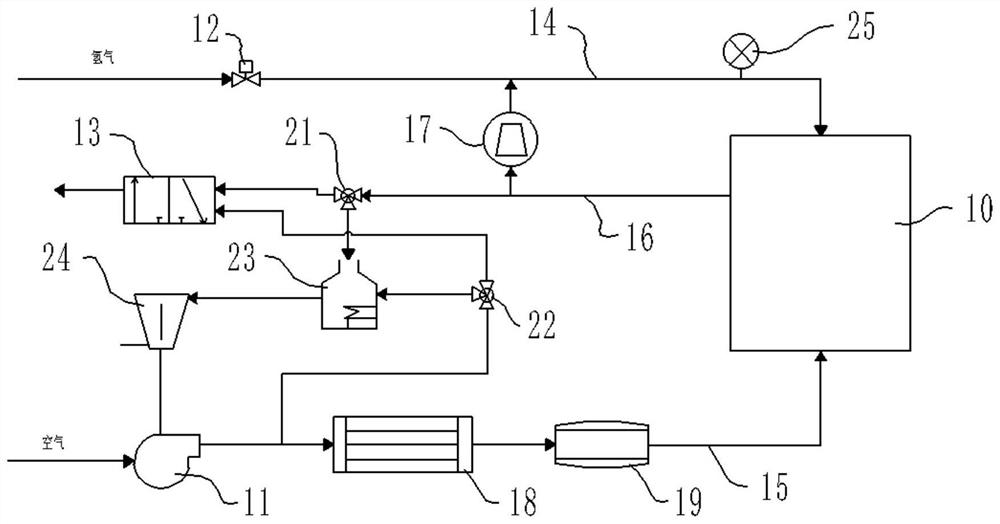
[0056] like figure 1 As shown, the fuel cell includes a stack 10 , an air compressor 11 , a hydrogen injection device 12 and a tail exhaust 13 .

[0057] The stack 10 is the core component of the fuel cell, and the anode hydrogen inlet of the stack 10 is connected to the hydrogen injection device 12 through the hydrogen inlet pipeline 14, so as to deliver the hydrogen required for the electrochemical reaction in the stack 10 through the hydrogen injection device 12; The cathode air inlet of the stack 10 is connected to the air compressor 11 through the air inlet pipe 15 to convey the oxygen required for the electrochemical reaction to the stack 10 through the air compressor 11 , and the oxygen contains the compressed air delivered by the air compressor 11 in the air. The anode hydrogen outlet of the stack 10 is connected to the tail row 13 through a hydrogen discharge pipeline 16 , so that the unreacted but remaining hydrogen in the stack 10 is discharged through the tail row...

Embodiment 2

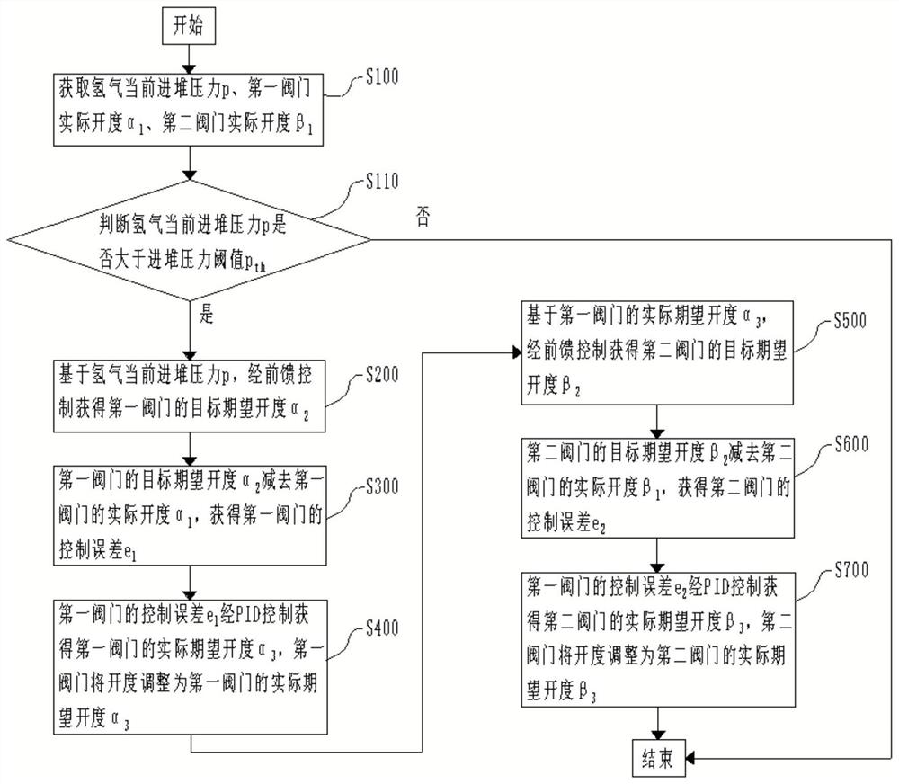
[0096] like image 3 , Figure 7 , Figure 8 as well as Figure 9 As shown, this embodiment also provides another control method for the exhaust gas treatment system of the fuel cell, and the control method includes the following steps:

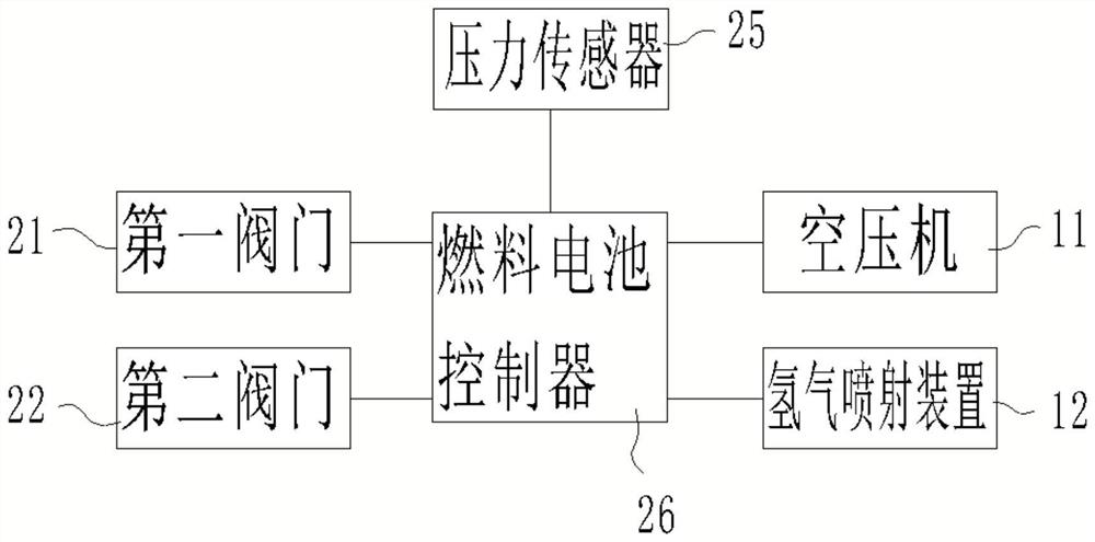
[0097] S100: The fuel cell controller 26 obtains the current pressure p of hydrogen in the hydrogen inlet pipeline 14 of the stack, and the actual opening degree α of the first valve 211 1 and the actual opening β of the second valve 22 1 . Among them, the actual opening degree α of the first valve 21 1 It is obtained through the opening sensor on the first valve 21 and transmitted to the fuel cell controller 26 through a hard-wired signal; the actual opening β of the second valve 22 1 It is obtained through the opening sensor on the second valve 22, and is transmitted to the fuel cell controller 26 through a hard-wired signal; the current pressure p of hydrogen into the stack is obtained through the pressure sensor 25 set on the first ...


PUM


Abstract

The invention discloses a tail gas treatment system of a fuel cell and a control method, and belongs to the technical field of fuel cells. According to the tail gas treatment system, a hydrogen inlet end of a combustor is connected with a hydrogen discharging pipeline of a galvanic pile through a first valve, and a gas inlet end of the combustor is connected with a gas inlet pipeline of the galvanic pile through a second valve, so that hydrogen discharged by the galvanic pile of a fuel cell enters the combustor for combustion; and the explosion risk possibly caused by directly discharging hydrogen from the tail gas of the fuel cell is solved. Moreover, the tail gas end of the combustor is connected with the gas inlet end of the expansion machine, high-temperature and high-pressure tail gas generated after combustion of the combustor acts on the expansion machine to drive the rotor shaft of the expansion machine to rotate, and the rotor shaft of the expansion machine is connected with the rotor shaft of the air compressor of the fuel cell, so that the air compressor provides power, and the parasitic power consumption of the air compressor is reduced.

Description

technical field [0001] The present application belongs to the technical field of fuel cells, and in particular relates to a fuel cell exhaust gas treatment system and a control method. Background technique [0002] The proton exchange membrane fuel cell is a device that uses hydrogen and oxygen to generate electricity by redox reaction in the stack. The air compressor transports air (oxygen) into the cathode of the stack, and the hydrogen injection device transports hydrogen into the anode of the stack. , the two react in the proton exchange membrane. During the reaction, the unreacted air and hydrogen in both the cathode and anode of the stack are discharged from the outlets of the two poles, respectively. [0003] In order to improve the utilization rate of hydrogen, in the existing technology, a hydrogen circulation pump is generally arranged at the anode outlet, and the hydrogen discharged from the stack anode is circulated back to the anode inlet. However, in order to...

Claims


Application Information

Patent Timeline
Patent Type & Authority Applications(China)
IPC IPC(8): H01M8/0662H01M8/04089
CPCH01M8/0662H01M8/04089Y02E60/50
Inventor 王明锐徐李瑶夏沙宫熔沙军
Owner DONGFENG MOTOR GRP
Learn More