
Conductive particle indentation detection equipment

A detection equipment and technology of conductive particles, applied in the field of optical detection, can solve the problems of poor quality consistency, difficult to control product quality stably, and high subjectivity of manual judgment, and achieve the effect of strong consistency, accurate detection effect and cost saving.

Pending Publication Date: 2022-07-12
厦门福信光电集成有限公司
View PDF7 Cites 1 Cited by
  • Summary
  • Abstract
  • Description
  • Claims
  • Application Information

AI Technical Summary

Problems solved by technology

[0002] With the rapid development of modern society, people's lives are rich and colorful, and there are more and more modern products to meet people's lives, among which electronic products account for a large part. The display screens on electronic products are mainly LCD screens. The use effect is directly reflected in the quality of the screen, and the quality is reflected in the processing and testing processes. At present, the vast majority of liquid crystal cell glass and IC devices are connected using COG technology (die-glass bonding technology). The ACF (Anisotropic Conductive Film) is mainly used for connection, and whether the particle arrangement is uniform determines the quality, so the detection process is very important. At present, the detection of conductive particles in COG technology is mainly done manually through a microscope after hot pressing. Observe the particles to judge whether the indentation is qualified and whether the conductive particles are uniform. However, manual judgment is very subjective, and the probability of errors in long-term observation by human eyes is also very high. The most important thing is that the quality of the product is difficult to control stably. poor consistency

Method used


Image

  • Conductive particle indentation detection equipment
  • Conductive particle indentation detection equipment
  • Conductive particle indentation detection equipment

Examples


Embodiment

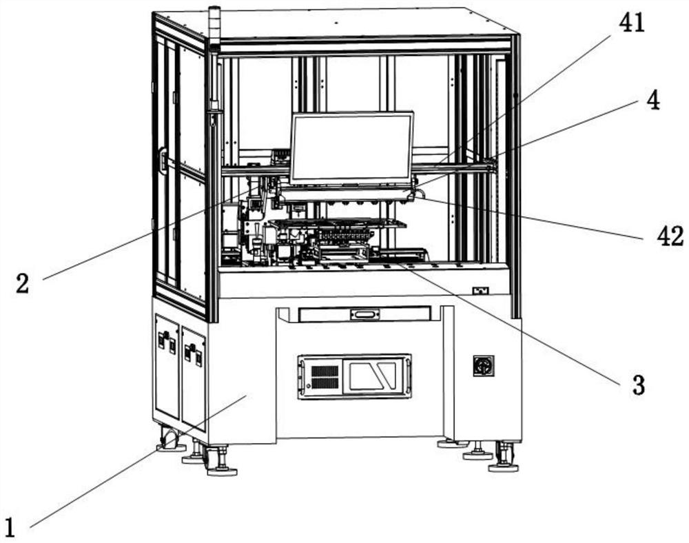
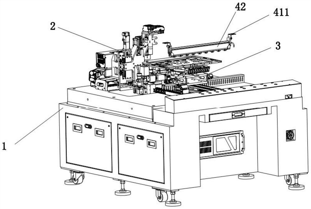
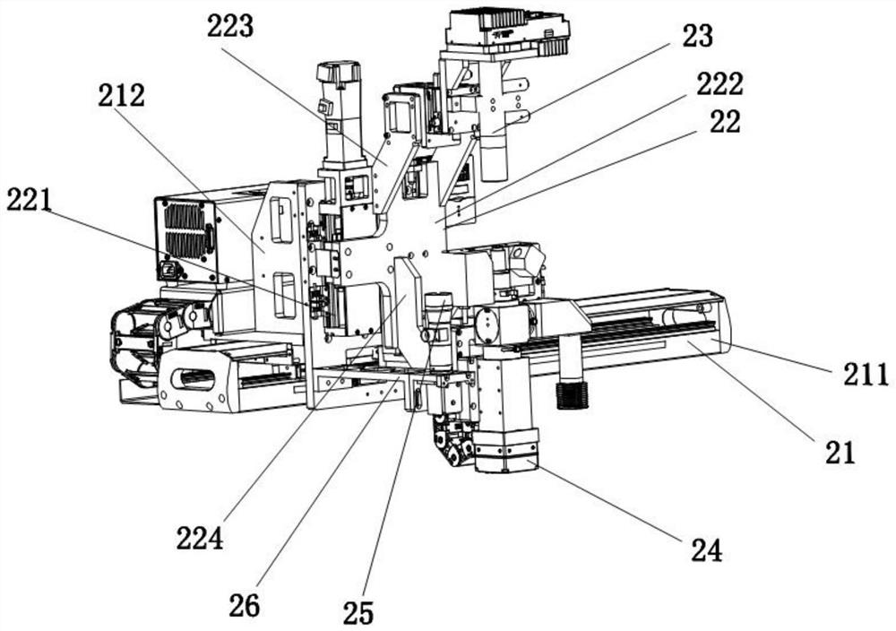
[0027] Cooperate Figure 1 to Figure 8 As shown, the present invention discloses a conductive particle indentation detection device, including a base 1, a detection mechanism 2 and a inspection mechanism 3. The detection mechanism 2 includes a line scan drive assembly 21, a camera stage 22, an offset detection assembly 23 and The particle detection component 24, the offset detection component 23 and the particle detection component 24 are respectively disposed on the upper side and the lower side of the camera stage 22 opposite to each other, and the line scan drive component 21 is used to drive the camera stage 22 to move along the detection direction to perform line scan detection , the feeding component 3 is used to transport the sample to be tested between the deviation detection component 23 and the particle detection component 24 . The offset detection component 23 is used to detect the offset status of the marks of the LCD screen, and the particle detection component 24...


PUM


Abstract

A conductive particle indentation detection device disclosed by the present invention comprises a base, a detection mechanism and an inspection mechanism, the detection mechanism comprises a line scanning driving assembly, a camera carrying table, an offset detection assembly and a particle detection assembly, and the offset detection assembly and the particle detection assembly are oppositely arranged on the upper side and the lower side of the camera carrying table respectively. The linear scanning driving assembly is used for driving the camera platform deck to move in the detection direction for linear scanning detection, and the feeding assembly is used for conveying a sample to be detected to the position between the offset detection assembly and the particle detection assembly. According to the conductive particle indentation detection equipment provided by the invention, feeding is carried out through the inspection mechanism, the particle detection camera and the offset detection camera are driven by the linear scanning driving assembly to automatically carry out linear scanning detection, manpower is replaced, the adverse effect of human participation on product contact is eliminated, the product cannot be damaged, the labor intensity is reduced, and the cost is saved.

Description

technical field [0001] The invention relates to the technical field of optical detection, in particular to a conductive particle indentation detection device. Background technique [0002] With the rapid development of modern society, people's lives are rich and colorful, and there are more and more modern products to meet people's lives, of which electronic products occupy a large part. The display screens on electronic products are mainly LCD screens. The effect of use is directly reflected in the quality of the screen, and the quality is reflected in the processing and testing processes. At present, most of the liquid crystal cell glass and IC devices are connected by COG technology (die-glass bonding technology). In COG technology ACF (anisotropic conductive film) is mainly used for connection, and the uniformity of the particle arrangement determines the quality, so the detection process is very important. At present, the detection of conductive particles in COG technol...

Claims


Application Information

Patent Timeline
Patent Type & Authority Applications(China)
IPC IPC(8): G02F1/13
CPCG02F1/1309
Inventor 洪亚德林中龙王士奇
Owner 厦门福信光电集成有限公司
Learn More