Ceramic atomizing core structure and preparation method thereof

An atomizing core and ceramic technology, applied in the field of atomization structure of electronic atomizer, can solve the problems of insufficient atomization effect, limited atomization area, and taste not as good as cotton core, etc. The effect of uniform atomization flow and strong anti-oxidation ability

Pending Publication Date: 2022-07-12
深圳雾道科技有限公司
View PDF0 Cites 1 Cited by
  • Summary
  • Abstract
  • Description
  • Claims
  • Application Information

AI Technical Summary

Problems solved by technology

[0004] The present invention aims to at least solve the problem in the prior art that "the atomization area is limited, the oil conduction is insufficient and burnt easily occurs, the heating area and the atomization area are concentrated in a localized area, so that the effect of atomization is not sufficient, and the taste is restored. Not as good as cotton core" technical problem

Method used


Image

  • Ceramic atomizing core structure and preparation method thereof
  • Ceramic atomizing core structure and preparation method thereof
  • Ceramic atomizing core structure and preparation method thereof

Examples


Embodiment 1

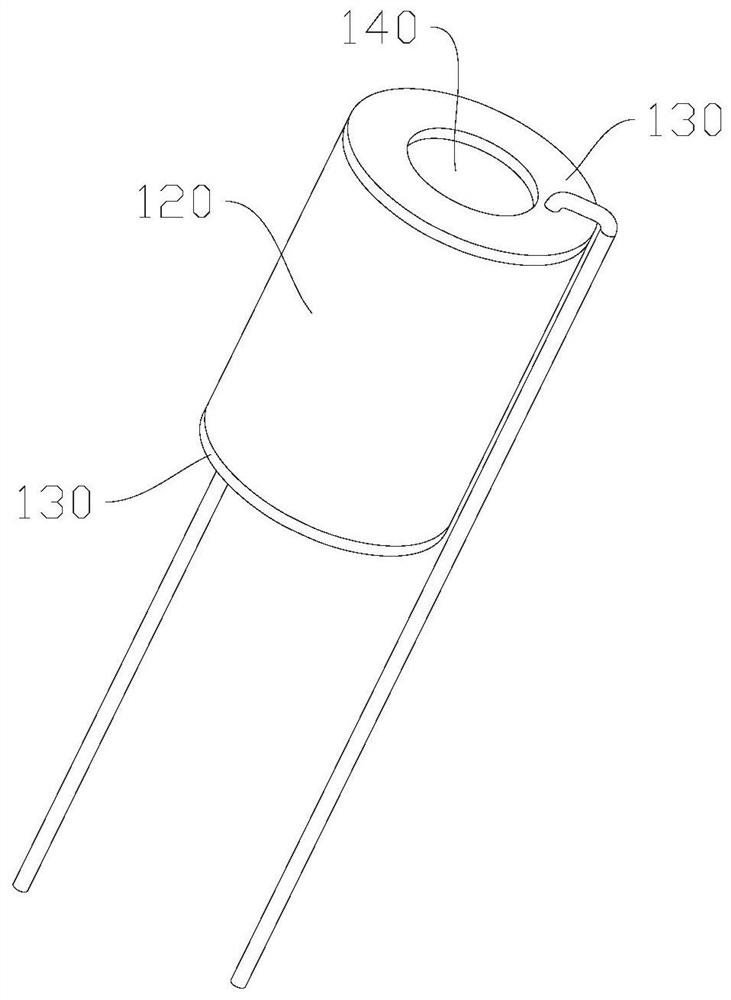
[0054] like Figure 1-Figure 4 As shown in the figure, the structure of the ceramic atomizing core is cylindrical. Specifically, an atomization channel 140 is formed in the middle of the cylindrical body. The cylindrical body is divided into an outer ring and an inner ring. It is made of oleoceramic 120 material, and electrode conductors 130 are attached to the end faces on both sides of the cylinder. The oil-conducting ceramic 120 sucks the atomized liquid contacted by the outer ring into the outer ring, and penetrates the atomized liquid into the conductive heating ceramic 110 through its porous nature. When the liquid contacts the heated conductive heating ceramic 110, it is atomized into oil mist, which flows from the atomization channel 140 in the middle of the cylindrical shape. The oil guiding area is large enough, and the whole surrounding can be effectively contacted with the atomized liquid. The direction of the air intake and the direction of the flue gas can be st...

Embodiment 2

[0056] like Figure 5-Figure 8 As shown, the structure of the ceramic atomizing core is in the shape of a boat, specifically, in a semicircle shape, one end of the semi-cylindrical plane is recessed inward to form an oil storage cavity 150, the inner ring of the semi-cylindrical is an oil-conducting ceramic 120, and the outer ring is a conductive heating ceramic 110. The conductive heating ceramic 110 is covered on the arc surface side of the oil conductive ceramic 120 , the electrode conductors 130 are attached to both ends of the conductive heating ceramic 110 , and the outer side of the conductive heating ceramic 110 is the atomization channel 140 . During the sucking process, the atomized liquid is injected into the oil storage cavity 150, and the atomized liquid evenly extends into the oil-conducting ceramics 120, and is transferred to the conductive heating ceramics 110 to be heated and atomized. The atomized atomization liquid flows along the atomization channel 140 out...

Embodiment 3

[0059] like Figure 9 and Figure 10 As shown in the figure, the structure of the ceramic atomizing core is in the shape of a block. Specifically, the oil-conducting ceramic 120 is in the shape of a square. One side of the oil-conducting ceramic 120 is grooved, the conductive heating ceramic 110 is arranged in the groove, and the electrode conductor 130 is arranged in the conductive On both sides of the heating ceramic 110 , the outer surface of the conductive heating ceramic 110 is an atomization channel 140 . The atomized liquid in the oil-conducting ceramic 120 penetrates into the conductive heating ceramic 110 , and the atomized liquid is heated to form an oil mist from the outer surface of the conductive heating ceramic 110 . It is suitable for the structure of the atomizer with a relatively flat shape.

[0060] The oil-conducting ceramic 120 can also be provided with a through groove, the through-groove is arranged through, the conductive heating ceramic 110 is arrange...


PUM


Abstract

The invention discloses a ceramic atomization core structure and a preparation method thereof, and relates to the technical field of electronic atomizer atomization structures, and the ceramic atomization core structure comprises conductive heating ceramic, oil guide ceramic and an electrode conductor; the oil guide ceramic and the conductive heating ceramic are integrally formed; one side of the conductive heating ceramic is connected with the oil guide ceramic, the other side of the conductive heating ceramic is communicated with the atomization channel, and the electrode conductors cover the head and tail ends of the conductive heating ceramic. According to the ceramic atomizing core structure and the preparation method thereof, the oil guide ceramic and the conductive heating ceramic have good corrosion resistance. The atomized liquid of the oil guide ceramic can be uniformly diffused into the conductive heating ceramic, and the conductive heating ceramic is large in heating area, stable in heating performance, capable of uniformly heating the atomized liquid in contact with the conductive heating ceramic, not prone to coking and gelatinization, large in atomization amount and high in reduction degree. The electrode conductor can accurately control the temperature of the conductive heating ceramic, the oxidation resistance is higher, and the service life is prolonged. Atomized oil mist flows along the atomization channel, the atomization flow is more uniform, and the atomization effect is better.

Description

technical field [0001] The invention relates to the technical field of atomization structures of electronic atomizers, in particular to a ceramic atomization core structure and a preparation method thereof. Background technique [0002] The mainstream atomizing ceramic cores of conventional electronic atomizers on the market are divided into two categories: microporous coated ceramics and mesh buried ceramics. These two types of ceramics have their own advantages and disadvantages in atomization performance and taste performance. Microporous film-coated ceramics are mainly made of microporous ceramics as the matrix, using the thick film printing process of metal paste, and by coating the surface of the ceramics. Although its advantages are simple and convenient to assemble, its atomization area is limited, and its atomization taste, explosion and reduction degree are not as good as cotton wick. The mesh buried ceramic is mainly made of ceramic micropores as the matrix, and ...

Claims


Application Information

Patent Timeline
Patent Type & Authority Applications(China)
IPC IPC(8): A24F40/46A24F40/48A24F40/10A24F40/70C04B35/04C04B35/58C04B35/10C04B35/14C04B35/56C04B35/565C04B35/622C04B38/06
CPCA24F40/46A24F40/48A24F40/10A24F40/70C04B38/0645C04B35/58014C04B35/58021C04B35/5611C04B35/58078C04B35/5626C04B35/56C04B35/58071C04B35/5622C04B35/58092C04B35/10C04B35/14C04B35/04C04B35/565C04B35/622
Inventor 袁树青
Owner 深圳雾道科技有限公司
Why Eureka
Try Eureka