
Unmanned aerial vehicle targeting flight training track

A flight training and unmanned aerial vehicle technology, which is applied in the direction of simulators, space navigation equipment, space navigation condition simulation devices, etc. It is not conducive to the in-depth development of programming courses and other issues, so as to achieve the effect of not being easy to go off-track, easy to implement, and simple in structure

Inactive Publication Date: 2022-07-08
浙江安防职业技术学院
View PDF0 Cites 0 Cited by
  • Summary
  • Abstract
  • Description
  • Claims
  • Application Information

AI Technical Summary

Problems solved by technology

And because of its strong operability and easy programming and control, UAV operation and programming courses are also promoted in primary and secondary education, but in the process of education, students can only conduct flight training in open places such as squares or playgrounds , and in micro-rotor drone programming competitions, drones are usually required to perform work such as material identification, material delivery, destination identification, material delivery, and flight shooting, while conventional drones have a single practical function and can The content of programming is less, and the teaching of drones cannot be carried out well, which is not conducive to the in-depth development of programming courses, and cannot reflect the performance of drones and the level of operators

Method used


Image

  • Unmanned aerial vehicle targeting flight training track
  • Unmanned aerial vehicle targeting flight training track
  • Unmanned aerial vehicle targeting flight training track

Examples


Embodiment Construction

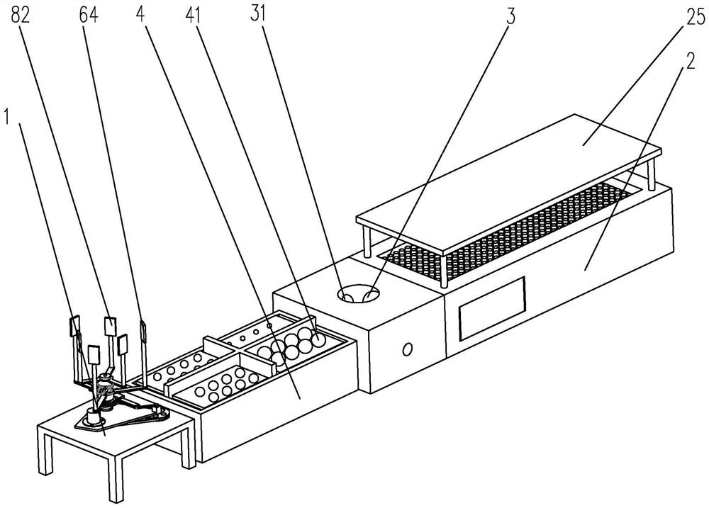
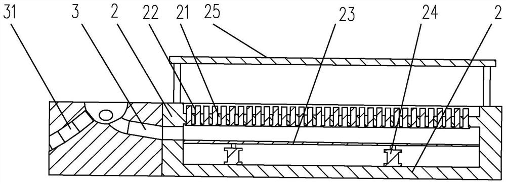
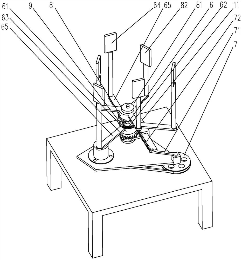
[0023] The embodiment of the drone targeting flight training track of the present invention is for example Figure 1 to Figure 3Shown: including a frame body, the frame body is sequentially provided with a take-off and landing platform, a flight platform 2 and a target shooting platform 1, the flight platform 2 forms a flight channel, and the target shooting platform 1 is provided with a rotating shaft 6, a drive The wheel 7 and the driving motor for driving the driving wheel 7 to rotate. The driving wheel 7 is provided with a swing rod 71 in the radial direction. Rod 72, the rotating shaft 6 is rotatably arranged on the target shooting platform 1, the rotating shaft 6 is also sleeved with a sliding sleeve 11, a transmission member 61 and a driven bevel gear 8 in sequence, and one side of the sliding sleeve 11 is provided with a A sliding groove, the driving rod 72 is slidingly matched with the sliding groove, one end of the transmission member 61 is formed with a transmission...


PUM


Abstract

The invention discloses an unmanned aerial vehicle target shooting flight training racing track which comprises a take-off and landing platform, a flight platform and a target shooting platform, a flight channel is formed in the flight platform, a rotating shaft and a driving wheel are arranged on the target shooting platform, a driving rod is rotationally connected to the driving wheel, and the rotating shaft is rotationally arranged on the target shooting platform; a sliding groove is formed in one side of the sliding sleeve, the driving rod is in sliding fit with the sliding groove, a transmission straight gear is formed at one end of the transmission part, a transmission bevel gear is arranged at the other end of the transmission part, a first target is arranged on the transmission part, and the transmission straight gear is meshed with the driving rod; a reversing bevel gear is further rotationally arranged on the rotating shaft and located between the driven bevel gear and the transmission bevel gear, a second target is connected to the driven bevel gear, and the flight channel is as high as the first target and the second target. The operation flight target shooting ability of the unmanned aerial vehicle can be fully tested, potential and interests of participants can be better stimulated, and unmanned aerial vehicle design and development of programming courses are facilitated.

Description

technical field [0001] The invention relates to the technical field of unmanned aerial vehicles, in particular to an unmanned aerial vehicle targeting flight training track. Background technique [0002] UAVs can be divided into fixed-wing, rotary-wing and flapping-wing UAVs according to their flight characteristics. Among them, micro-rotor UAVs have the characteristics of small size, simple structure and flexible control. They can take off and land vertically. Hovering freely, it can also adapt to various natural environments, and has the advantages of autonomous flight and landing capabilities, and can operate in some complex and dangerous environments that are not suitable for humans to enter. And because of its strong operability and easy programming and control, UAV operation and programming courses have also been promoted in primary and secondary education. However, during the education development process, students can only conduct flight training in open spaces such ...

Claims


Application Information

Patent Timeline
IPC IPC(8): G09B9/48G09B19/00
CPCG09B9/48G09B19/0053
Inventor 黄友余翁耀炜厉玲婷
Owner 浙江安防职业技术学院
Learn More