
Stainless steel plate deburring equipment for high-voltage switch cabinet

A high-voltage switchgear and stainless steel technology, which is applied to machine tools, metal processing equipment, grinding/polishing equipment, etc., which are suitable for grinding the edge of workpieces, and can solve the problem of burr cleaning equipment without a transmission structure, low grinding efficiency, and difficult to grind parts Replacement and other issues to achieve the effect of avoiding shaking, improving grinding efficiency and reducing error rate

Pending Publication Date: 2022-07-08
CHINA SCI TIANGONG ELECTRICAL HLDG
View PDF9 Cites 1 Cited by
  • Summary
  • Abstract
  • Description
  • Claims
  • Application Information

AI Technical Summary

Problems solved by technology

[0002] High-voltage switchgear refers to the function of on-off, control or protection in power system power generation, transmission, distribution, power conversion and consumption. In the production technology of high-voltage switchgear, the shell material of high-voltage switchgear is generally made of stainless steel, stainless steel After the plate is cut, the burr on the stainless steel plate exists at the edge of the edge, and it needs to be polished with burr cleaning equipment, but the common deburring equipment can only be polished on one side, the grinding efficiency is low, and it is not easy to replace the polished parts. The deburring equipment does not have a transmission structure and can only achieve fixed position grinding

Method used


Image

  • Stainless steel plate deburring equipment for high-voltage switch cabinet
  • Stainless steel plate deburring equipment for high-voltage switch cabinet
  • Stainless steel plate deburring equipment for high-voltage switch cabinet

Examples


Embodiment Construction

[0030] In order to further illustrate the technical means and effects adopted by the present invention to achieve the predetermined purpose of the invention, the specific embodiments, structures, features and effects of the present invention are described in detail below in conjunction with the accompanying drawings and preferred embodiments.

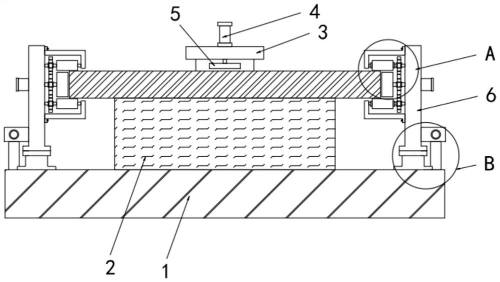
[0031] see Figure 1-Figure 6 As shown, the present invention provides a stainless steel plate deburring equipment for high-voltage switch cabinets, including a processing table 2, a stainless steel plate is placed on the top of the processing table 2, support columns 6 are installed on both sides of the processing table 2, and the processing table 2 The end surface of the stainless steel plate is equipped with a grinding mechanism for grinding the stainless steel plate;

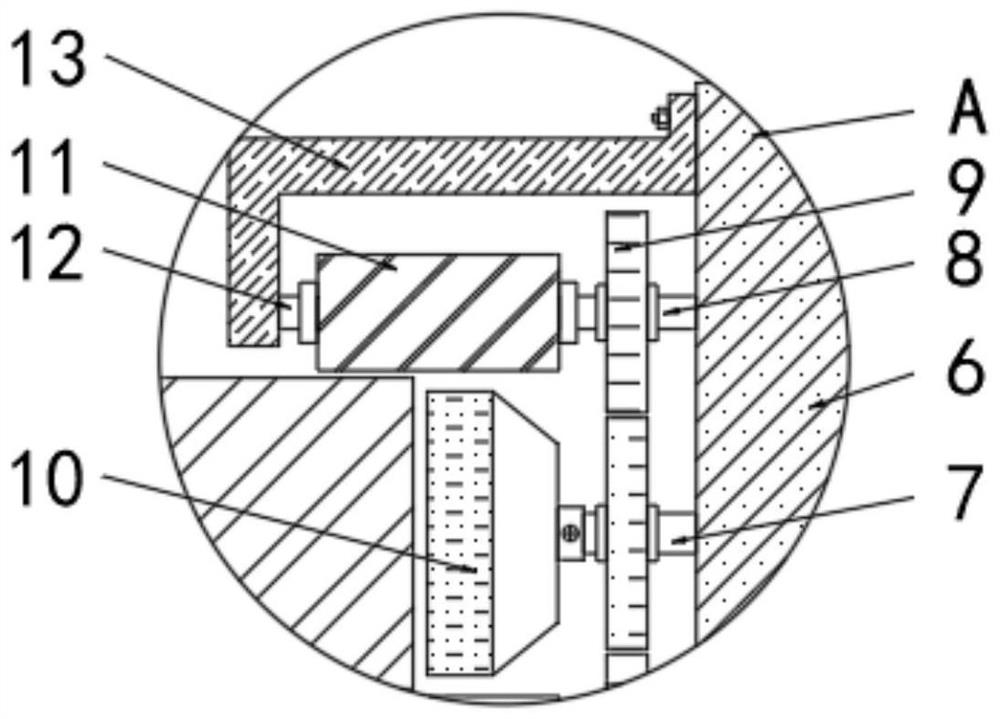
[0032] The grinding mechanism includes two upper and lower sanding rollers 11 and sanding paper 10. One end of the sanding paper 10 is connected with the main shaft 7...


PUM


Abstract

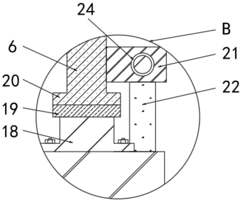
The invention discloses stainless steel plate deburring equipment for a high-voltage switch cabinet, and particularly relates to the technical field of high-voltage switch cabinet machining. An upper grinding roller, a lower grinding roller and grinding paper make contact with the cutting section of a stainless steel plate, and the grinding paper grinds the section of the stainless steel plate; the upper grinding roller and the lower grinding roller are driven by the driven shaft to grind the section of the stainless steel plate, grinding of the upper surface, the lower surface and the side surface of the stainless steel plate is achieved, the deburring effect is guaranteed, the grinding efficiency is improved, meanwhile, the grinding rollers and the supporting frame are designed to be of a detachable structure, the guide blocks enter the guide grooves, and the grinding efficiency is improved. The synchronous transmission of the grinding roller and the driven shaft is realized; the grinding mechanism is matched with the sliding table to slide on the linear guide rail, drives the supporting column to move in the same direction and drives the upper grinding roller, the lower grinding roller and the grinding paper in the grinding mechanism to do reciprocating linear motion on the section of the stainless steel plate, the grinding automation degree is improved, and the efficiency is high.

Description

technical field [0001] The invention relates to the technical field of high-voltage switch cabinet processing, in particular to stainless steel plate deburring equipment for high-voltage switch cabinets. Background technique [0002] High-voltage switchgear refers to the functions of on-off, control or protection in the power generation, transmission, distribution, power conversion and consumption of the power system. In the production technology of high-voltage switchgear, the shell material of high-voltage switchgear is generally made of stainless steel, stainless steel After the plate is cut, the burrs on the stainless steel plate are at the edge of the rib, which needs to be polished with a burr cleaning equipment, but the common deburring equipment can only perform single-sided grinding, the grinding efficiency is low, and it is not easy to replace the grinding parts. The burr cleaning equipment does not have a transmission structure, and can only achieve grinding in a ...

Claims


Application Information

Patent Timeline
Patent Type & Authority Applications(China)
IPC IPC(8): B24B9/04B24B27/00B24B41/02B24B41/00B24B47/12B24B1/00
CPCB24B9/04B24B27/0076B24B27/0092B24B41/02B24B41/00B24B47/12B24B1/00
Inventor 张帆马勇周俊曹征俊虞强汤金龙严茜茜
Owner CHINA SCI TIANGONG ELECTRICAL HLDG
Learn More