Micro-fluidic chip and application thereof
A microfluidic chip, chip technology, applied in laboratory containers, enzymology/microbiology devices, methods of supporting/immobilizing microorganisms, etc., can solve the problem of inability to remove cryoprotectants, weak removal ability, and cell recovery rate lower problem
- Summary
- Abstract
- Description
- Claims
- Application Information
AI Technical Summary
Problems solved by technology
Method used
Image

Examples
Embodiment 1
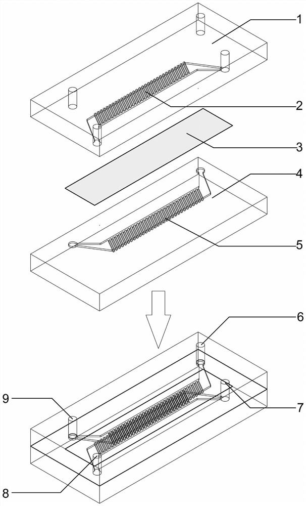
[0051] has as figure 1 A microfluidic chip of the shown structure includes:
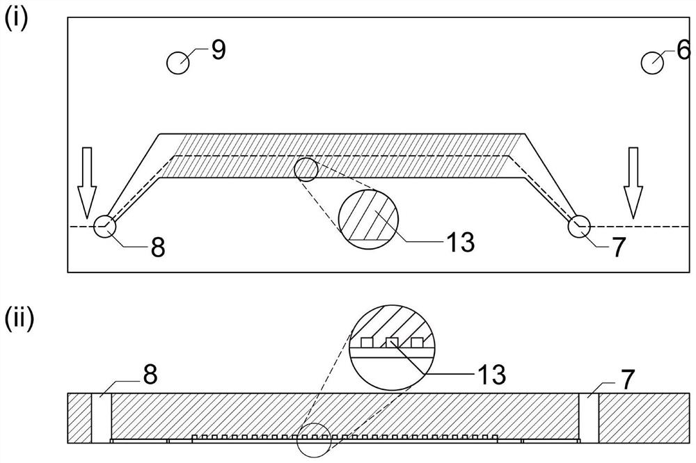
[0052] The microfluidic chip has a rectangular first chip 1 and a second chip 4 with a length, width and height of 4 cm, 2 cm and 0.5 cm respectively; the material of the first chip 1 and the second chip 4 is polydimethylsiloxane. The first lower surface of the first chip 1 includes a first channel 2, the depth of which is 40 μm, the width of the main part (ie the part of the shrink-like structure without the inlet and outlet) is 1 mm, and the length is 1.5 cm. An array of inclined trenches 13 is constructed in the first channel 2 on the first lower surface of the first chip 1. The width of the trenches 13 is 25 μm and the depth is 25 μm. The angle between the axial direction of the trench 13 and the long sidewall of the first channel 2 is 60°, the spacing between the grooves 13 is 25 μm, and the array of grooves 13 is filled with straight channel parts.
[0053] like figure 2 As shown, the first...
Embodiment 2
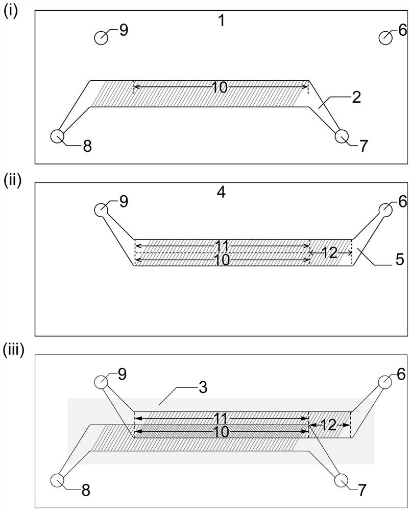
[0059] In the embodiment of the present invention, the first channel 2 is a flow cavity located on the first lower surface of the first chip 1 , and the second channel 5 is a flow cavity located on the second upper surface of the second chip 4 . The first channel 2 and the second channel 5 are similar in shape, and the flow chamber can be divided into inlet and outlet portions at both ends and a main body chamber portion in the middle. A layer of porous membrane 3 is sandwiched between the first chip 1 and the second chip 4 . The surfaces of the first chip 1 and the second chip 4 with channels are attached to each other. The first chip 1 and the second chip 4 are placed in parallel, and after the main body cavity parts are completely aligned and overlapped, they are staggered by a distance in the lateral and longitudinal directions respectively, so as to achieve the effect of the main body cavity parts being overlapped. The overlapping part of the main body cavity of the seco...
Embodiment 3
[0061] In the embodiment of the present invention, the depth of the first channel 2 is smaller than the thickness of the first chip 1 , and the depth of the second channel 5 is smaller than the thickness of the second chip 4 . The overlapping part of the first channel 2 and the second channel 5 is the dialysis zone 10, and its position and shape are as follows: figure 2 shown in.
[0062] figure 2 Among them, the first inlet 8 is the cleaning liquid inlet, and the first outlet 7 is the cleaning liquid outlet. In the embodiment of the present invention, the first channel 2 is a cleaning solution channel, and the isotonic cleaning solution without cryoprotectant enters the chip at a fixed flow rate from the first inlet 8 , and the second channel between the dialysis zone 10 and the second chip 4 The fluid in channel 5 is dialyzed. In the first channel 2 of the first chip 1, parallel, elongated (rectangular cross-section) protrusions are constructed, grooves 13 are formed be...
PUM
| Property | Measurement | Unit |
|---|---|---|
| Cell density | aaaaa | aaaaa |
Abstract
Description
Claims
Application Information
 - R&D
- Intellectual Property
- Life Sciences
- Materials
- Tech Scout
- Unparalleled Data Quality
- Higher Quality Content
- 60% Fewer Hallucinations
Browse by: Latest US Patents, China's latest patents, Technical Efficacy Thesaurus, Application Domain, Technology Topic, Popular Technical Reports.
© 2025 PatSnap. All rights reserved.Legal|Privacy policy|Modern Slavery Act Transparency Statement|Sitemap|About US| Contact US: help@patsnap.com