
Liquid mist defoaming device for falling film absorption tower

A technology of falling film absorption tower and absorption tower, which is applied in the field of liquid mist demisting device, can solve the problems of air, flowers, trees, air pollution, acid gas and alkaline gas, etc., so as to improve efficiency, gas The effect of smooth channel

Pending Publication Date: 2022-07-05
江苏嘉晟化工科技有限公司
View PDF11 Cites 0 Cited by
  • Summary
  • Abstract
  • Description
  • Claims
  • Application Information

AI Technical Summary

Problems solved by technology

[0002] Industrial production often produces a large amount of waste gas, especially containing a lot of acid gas and liquid droplets. If the waste gas is discharged into the atmosphere without treatment, it will pollute the air, pollute flowers, trees and other plants, so we need to treat the acid gas and liquid droplets in the waste gas For neutralization reaction and filtration, in the prior art, a wire mesh demister is installed in the falling film absorption tower. The wire mesh demister is mainly composed of a wire mesh, a wire mesh grid, a wire mesh block and a support device for fixing the wire mesh. , but there are still some problems: (1) Often the wire mesh demister can only filter larger droplets in the exhaust gas, and there are many small droplets that cannot be filtered, and will be discharged into the air with the gas, which is harmful to the air (2) The settled droplets after being filtered by the wire mesh demister have not been treated, and there is a lack of effective evaporation devices for the droplets; (3) Many acidic and alkaline gases are not easy to handle, and the lack of will A device that converts gas into liquid for filtration and settling

Method used


Image

  • Liquid mist defoaming device for falling film absorption tower
  • Liquid mist defoaming device for falling film absorption tower
  • Liquid mist defoaming device for falling film absorption tower

Examples


Embodiment

[0024] see Figure 1 to Figure 6 , the present invention provides a kind of technical scheme:

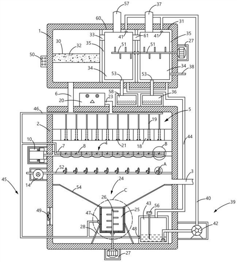
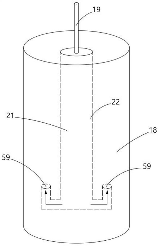
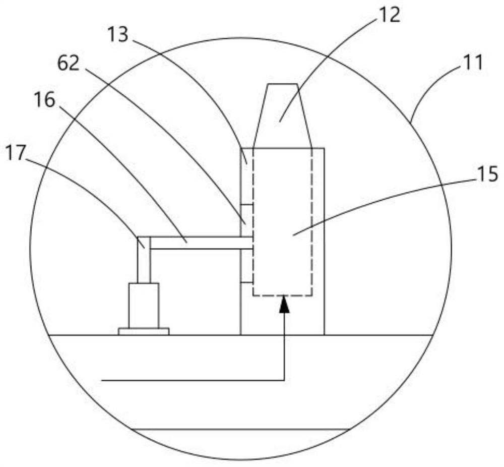
[0025] A liquid mist defoaming device for a falling film absorption tower, comprising an upper absorption tower 1 and a lower absorption tower 2, wherein the lower absorption tower 2 includes a first air inlet pipe 3, a liquid removal device 4, a liquefaction device 5 and The first air outlet pipe 6, the right side of the lower absorption tower 2 is connected with the first air inlet pipe 3, and the inner wall of the lower absorption tower 2 is welded with a liquid removing device 4, which is used to filter and remove the droplets in the liquid mist. A liquefaction device 5 is welded directly above the liquid removal device 4, which is used to liquefy and settle the gas in the waste gas into the liquid removal device 4. A first gas outlet pipe 6 is connected above the lower absorption tower 2 and extends to the upper absorption tower 1, so The liquid removing device 4 includes a fi...


PUM


Abstract

The invention provides a liquid mist defoaming device for a falling film absorption tower, which comprises an upper absorption tower and a lower absorption tower, the lower absorption tower comprises a first gas inlet pipe, a liquid removing device, a liquefying device and a first gas outlet pipe, and the right side of the lower absorption tower is communicated with the first gas inlet pipe; a liquid removal device used for filtering and removing liquid mist in waste gas is welded to the inner wall of the lower absorption tower and comprises a first filter screen, the first filter screen is welded to the middle of the interior of the lower absorption tower, through holes are evenly formed in the middle of the first filter screen, and cold air pipes with holes in the outer walls are embedded in the through holes. Liquid drops gathered at the bottoms of the filter screens can be quickly and effectively removed through the liquid removing device and the liquefying device, the smoothness of a gas channel is guaranteed, the evaporation efficiency can be improved through the evaporation device, non-acidic and alkaline gases are absorbed by installing the second filter screen, acidic and alkaline gases are neutralized by installing the reaction box, and environmental protection is facilitated.

Description

technical field [0001] The invention relates to the technical field of waste gas treatment, in particular to a liquid mist defoaming device for a falling film absorption tower. Background technique [0002] Industrial production often produces a large amount of waste gas, especially containing a lot of acidic gases and droplets. If the waste gas is discharged into the atmosphere without treatment, it will pollute the air and pollute plants such as flowers, plants and trees. For neutralization reaction and filtration, in the prior art, a wire mesh demister is installed in the falling film absorption tower. , but there are still some problems: (1) Often, the wire mesh demister can only filter the larger droplets in the exhaust gas, and there are many small droplets that cannot be filtered, and will be discharged into the air with the gas, which will not affect the air. It is harmful to flowers, plants and trees; (2) The droplets that settle after being filtered by the wire me...

Claims


Application Information

Patent Timeline
Patent Type & Authority Applications(China)
IPC IPC(8): B01D53/18B01D46/10B01D46/42B01D46/76B01D53/04B01D53/78B01D53/40B01D53/42B01D5/00B01D1/00B01D1/30
CPCB01D53/18B01D46/10B01D46/42B01D53/04B01D53/78B01D53/40B01D53/42B01D5/0012B01D1/0011B01D1/30Y02A50/2351
Inventor 郭建平陈培袁维泉
Owner 江苏嘉晟化工科技有限公司
Learn More