Spacer and image-forming apparatus, and manufacturing method thereof
An image and separator technology, applied in cold cathode manufacturing, electrode system manufacturing, discharge tube/lamp manufacturing, etc., to achieve the effects of high brightness, high mechanical strength, and high color purity
- Summary
- Abstract
- Description
- Claims
- Application Information
AI Technical Summary
Problems solved by technology
Method used
Image

Examples
example 1
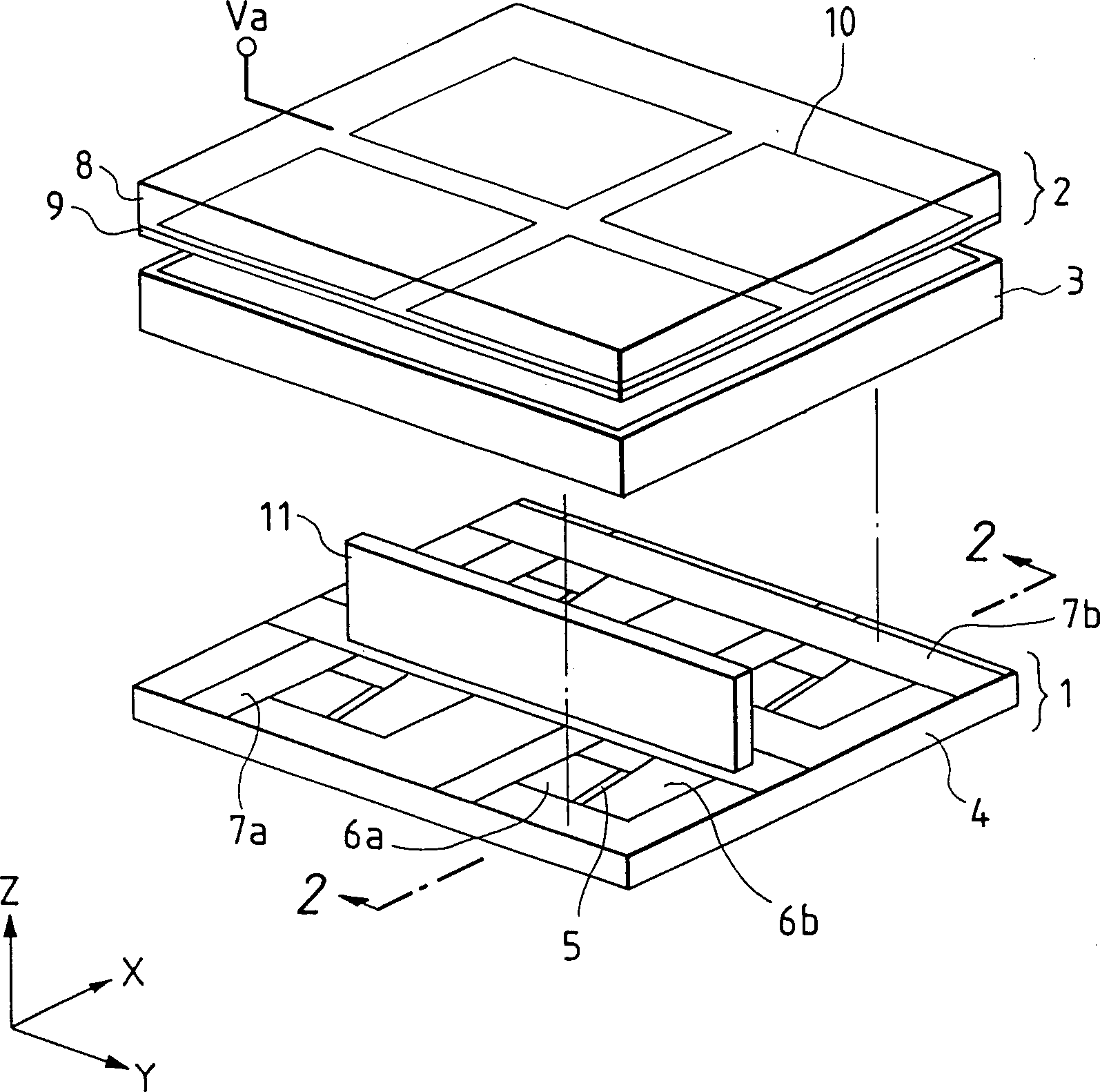
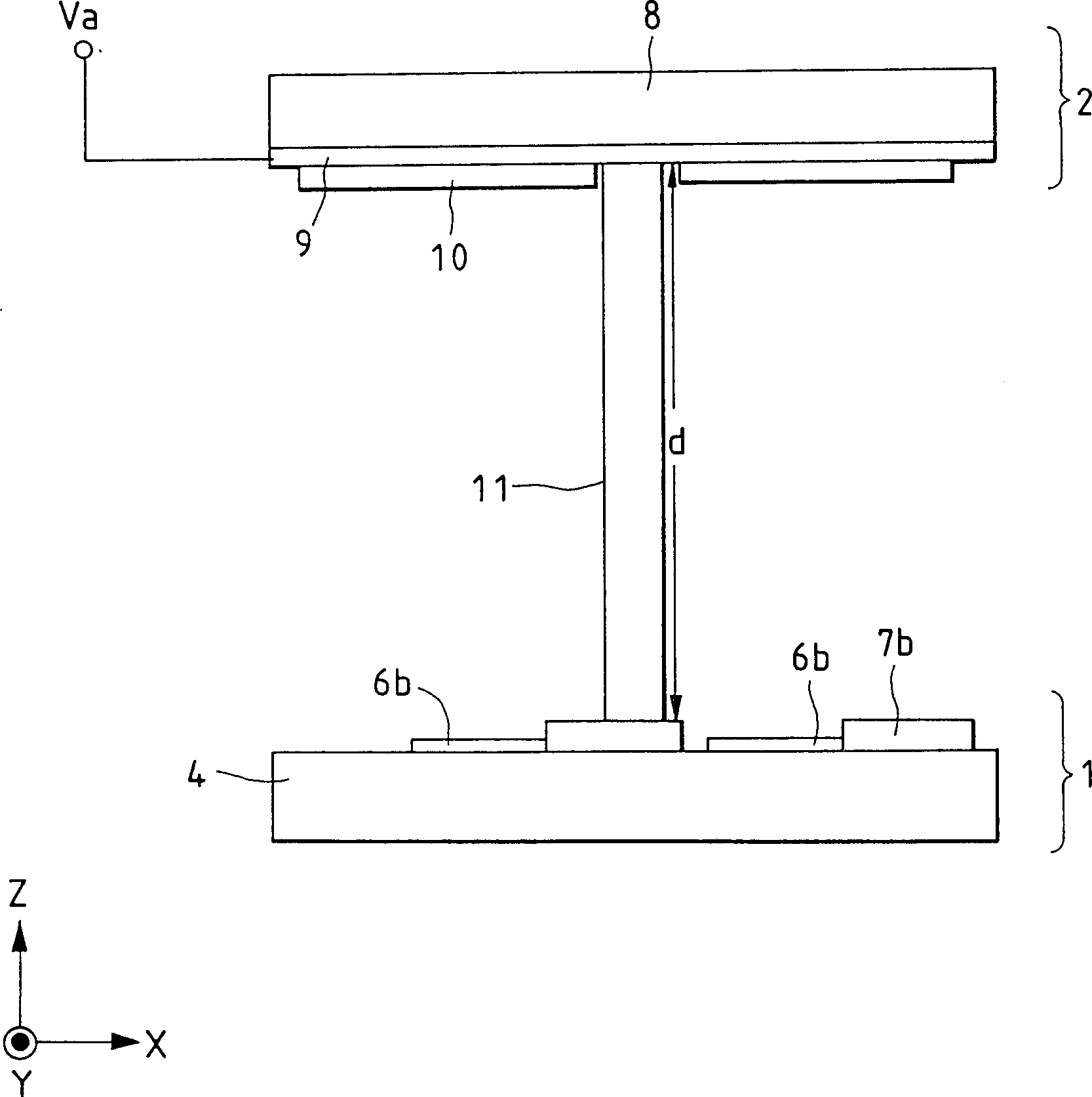
[0188] The basic structure and figure 1 and figure 2 The structure shown is the same, and the overall structure is shown in Figure 9, wherein, with figure 1 , 2 The same components as 8 are indicated by the same reference numerals. Reference numeral 91 denotes a metal back layer.
[0189] The method of manufacturing the image forming apparatus of the present invention such as Figure 10A to Figure 10H shown. Next, refer to Figure 9 and Figure 10A to Figure 10H The basic structure of the image forming apparatus of the present invention and its manufacturing method will be described. In this example, the substrate 4 itself has the function of the backplane, so in Figure 10A to Figure 10H and Figure 11 It is represented by the label 1 or 4 in it.
[0190] For simplicity, Figure 10A to Figure 10H The electron-emitting devices and the preparatory steps in their vicinity are shown, but this example provides an image forming apparatus formed by a simple matrix arrangem...
example 2
[0228] In this example, the process is the same as in Example 1 up to step h.
[0229] (step i)
[0230] In this example, a small glass plate cut and ground to a size of 1 x 40 x 0.2 mm was cleaned, and an amorphous polyimide solvent (Toray Co. . Toreniece #3000) for spin coating. The spin coating first constitutes a surface (1 x 40 mm face) and the glass sheet is prebaked on a hot plate at 100° C. for 10 minutes. Then, the other side was made by spin coating, and the glass piece was prebaked on a hot plate at 100°C for 10 minutes. Curing was performed by placing the coated glass sheet in a clean oven, raising the temperature from room temperature to 300°C, and then maintaining the glass sheet at 300°C for one hour. The polyimide resin thus obtained had a thickness of about 1 µm.
[0231] (step j)
[0232] On the upper wiring 7b of the backplane 1 at the position for placing the spacer, Toreniece #3000 was applied with a dispenser to temporarily fix the spacer 11 prepared...
example 3
[0253] In this example, the process is the same as in Example 1 up to step h.
[0254] (step i)
[0255] In this example, a cleaned glass rod with a diameter of 0.2 mmφ was diluted five times in volume with N-methyl-ethylpyrrolidone by immersing and detaching the glass rod from the liquid. ) for dip coating. Pre-bake the raised glass rod in a clean oven at 100°C for 10 minutes, and proceed by placing the glass rod in a clean oven, raising the temperature from room temperature to 300°C and maintaining it at 300°C for one hour solidify. The polyimide resin film thus obtained had a thickness of about 1 µm.
[0256] This glass rod surface-coated with polyimide resin was cut into a length of 1 mm to obtain a plurality of cylindrical partitions 11 .
[0257] (step j)
[0258] At the position for placing the spacer on the upper wiring 7b of the back plate 1, Toreniece #3000 was applied with a dispenser to temporarily fix the spacer 11 prepared in step i. In this operation, the ...
PUM
 Abstract
Description
Claims
Application Information
 - R&D
- Intellectual Property
- Life Sciences
- Materials
- Tech Scout
- Unparalleled Data Quality
- Higher Quality Content
- 60% Fewer Hallucinations
Browse by: Latest US Patents, China's latest patents, Technical Efficacy Thesaurus, Application Domain, Technology Topic, Popular Technical Reports.
© 2025 PatSnap. All rights reserved.Legal|Privacy policy|Modern Slavery Act Transparency Statement|Sitemap|About US| Contact US: help@patsnap.com